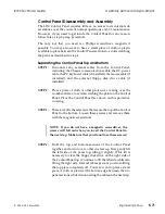
Control Panel Disassembly and Assembly
The 8150 Control Panel requires little or no access to its internal sub
assemblies over the course of normal operations and/or maintenance.
However, if you need to get inside the Control Panel for any reason,
follow this a step-by-step procedure.
The only tool that you need is a Phillips screwdriver, magnetic if
possible. You may also want to have a small piece of cloth or plastic
available to place between the Control Panel sections to avoid scratching
the paint, as described in step 4.
Separating the Control Panel Top and Bottom
STEP 1:
Disconnect any external cables from the Control Panel,
including: the Chassis communications cable, the DC power
cable, the PC keyboard cable (if installed), the mouse cable (if
installed), and the external floppy disk drive cable (if
installed).
STEP 2:
Place a piece of cloth or other protective covering over the
workbench area to avoid scratching the paint on the Control
Panel. Place the Control Panel face down on this protective
covering.
STEP 3:
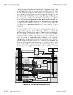
There are 10 flat head screws that secure the top of the Control
Panel to the bottom. Loosen these screws and remove them
with the magnetic screwdriver.
NOTE: If you do not have a magnetic screwdriver, the
screws will fall out when you invert the Control Panel in
the next step. Make sure that you do not lose these screws!
STEP 4:
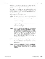
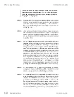
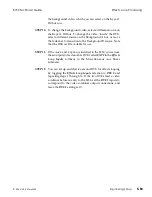
Hold the top and bottom sections of the Control Panel
together, and turn it over so that it is face up. First, gently lift
the left side of the panel top, tilting it slightly. (This tilt is
necessary to clear the floppy disk drive on the right side of
the Control Panel top.) Continue to lift the left side while also
lifting the right side. Internal cables prevent you from lifting
the top piece completely off. You may want to place a small
piece of cloth or plastic at the bottom edge between the two
panel sections while disconnecting the cables in the next step.
8150 Technical Guide
Assembly Removal /Replacement
9100-0212-04 - May 2000
Engineering Setup
5-71
Summary of Contents for ASWR8150
Page 12: ...Table of Contents 8150 Technical Guide X Contents 9100 0212 04 May 2000...
Page 39: ......
Page 80: ...Control Panel Connector Detail 8150 Technical Guide 2 40 Installation 9100 0212 04 May 2000...
Page 109: ...Option Installation 8150 Technical Guide 3 30 Option Installation 9100 0212 04 May 2000...
Page 236: ...8150 Partial Parts List 8150 Technical Guide A 6 Appendix 9100 0212 04 May 2000...

