STEP 1:
Power down the 8150 Signal Chassis. Remove the integral
front cover/air filter to access the 8150 Switcher board. Use
the Accom supplied tool to extract the Switcher board from
the chassis and lay it on a clean, static free, grounded work
surface.
NOTE: Seating the sub-board requires moderate pressure.
Ensure that the Switcher board is sufficiently supported so
it does not flex.
STEP 2:
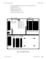
See Figure 3-14, on the following page, to locate the Color
Corrector or Color Corrector Bypass sub-board (J5 and
surrounding shaded area). Remove the screws that secure the
installed sub-board to the Switcher board, then remove the
sub-board.
STEP 3:
Note the orientation notch in J5 and orient the replacement
sub-board to match. Seat the sub-board on the connector and
press gently but firmly directly over the connector area so as
not to unduly flex the Switcher board. Fix the standoff
fastening screws to secure the sub-board. Use the Accom-
supplied tool to reseat the Switcher board in the 8150 Signal
Chassis.
STEP 4:
Power up the Signal Chassis. Select an appropriate video
signal on the Background A and Background B buses and
verify that you can mix or wipe between the two buses. Select
the source on Program and Preset and verify that you can mix
or wipe between the two buses.
Option Installation
8150 Technical Guide
3-22
Option Installation
9100-0212-04 - May 2000
Summary of Contents for ASWR8150
Page 12: ...Table of Contents 8150 Technical Guide X Contents 9100 0212 04 May 2000...
Page 39: ......
Page 80: ...Control Panel Connector Detail 8150 Technical Guide 2 40 Installation 9100 0212 04 May 2000...
Page 109: ...Option Installation 8150 Technical Guide 3 30 Option Installation 9100 0212 04 May 2000...
Page 236: ...8150 Partial Parts List 8150 Technical Guide A 6 Appendix 9100 0212 04 May 2000...


