GPI Outputs
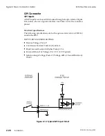
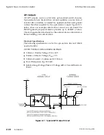
All GPI outputs work as solid state opto-isolated switch closures.
Opto-isolators have limited drive current capability, so some form of
external drive interface is needed for applications that need greater
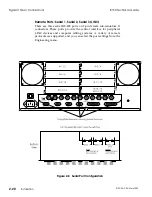
current than that supplied by the opto-isolator output. Figure 2-11,
below, shows an example current driver circuit you can build. The
2N2222 general purpose transistor provides up to 650mW of drive.
Check all applicable data sheets for the external devices shown below
before building your current driver.
Electrical Specifications
The following specifications are for the opto-isolator (device # 4N33)
used in the 8150.
OUTPUT DETECTOR MAXIMUM RATINGS
Collector - Emitter Voltage (V
CEO
): 30 V.
Emitter - Collector Voltage (V
ECO
): 5 V.
Collector Current - Continuous (I
C
): 150 mA.
Power Dissipation (P
D
): 150 mW.
Isolation Surge Voltage (Peak AC Voltage, 60Hz, 1 Second Duration):
7500 V.
Figure 2-11 Typical GPI Output Circuit
Signal Chassis Connector Detail
8150 Technical Guide
2-30
Installation
9100-0212-04 - May 2000
Summary of Contents for ASWR8150
Page 12: ...Table of Contents 8150 Technical Guide X Contents 9100 0212 04 May 2000...
Page 39: ......
Page 80: ...Control Panel Connector Detail 8150 Technical Guide 2 40 Installation 9100 0212 04 May 2000...
Page 109: ...Option Installation 8150 Technical Guide 3 30 Option Installation 9100 0212 04 May 2000...
Page 236: ...8150 Partial Parts List 8150 Technical Guide A 6 Appendix 9100 0212 04 May 2000...


