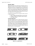
The 10-bit Component Analog Input module has dual color LEDs that
light green to indicate that the video or key input is present and
genlocked. Yellow indicates that the video or key sync input is present
but not genlocked, or does not match the system line standard. Red
indicates that there is no video or key sync present, or that there is no
input present at all.
Composite Analog Video + Key Input
This optional module supports one composite video input (either NTSC
or PAL, depending on the line standard selected), plus one analog key
input, both sampled at 10-bit resolution. These two inputs also include
a high impedance loop through for connection to other equipment.
Connect a 75-ohm terminator to the loop through if it is not used.
The Composite Analog Input module has dual color LEDs that light
green to indicate that the video or key input is present and genlocked.
Yellow indicates that the video or key sync input is present but not
genlocked, or does not match the system line standard. Red indicates
that there is no video or key sync present, or that there is no input present
at all.
Dual Parallel Digital Input
This optional module conforms to CCIR 601/SMPTE 125M parallel
component digital video standards. Input "A" connectors are odd
numbered inputs, and input "B" connectors are even numbered inputs.
Input horizontal retiming is automatic, with a range of one half line
advanced to two lines delayed from reference. Dual color LEDs appear
through an opening near each input connector. These LEDs light green
to indicate that the input is correct and genlocked. Yellow indicates that
the input is not genlocked or does not match the system line standard.
Unlit LEDs indicate that there is no input signal present.
Aux 3, 4 Output
This optional module conforms to CCIR 601/SMPTE 259M serial
component digital video standards. It must be installed in the 15/16
AUX 3/4 module location, which precludes using inputs 15 and 16. The
horizontal blanking, timing, and output bit resolution of this module
follow the settings in the Engineering menu. You can select the sources
for these outputs in the Miscellaneous menu. These outputs are delayed
by two lines, 18 lines, or 34 lines from reference, depending on the source
selected; you cannot select a one frame delay for these outputs. They are,
however, always zero timed to each other. The Aux Ref 2 output on this
module provides a dedicated (1 volt p-p) analog composite sync signal
that matches the vertical timing of the Aux 3 and 4 outputs. This lets you
genlock an external device that is being fed by these outputs.
Signal Chassis Connections
8150 Technical Guide
2-12
Installation
9100-0212-04 - May 2000
Summary of Contents for ASWR8150
Page 12: ...Table of Contents 8150 Technical Guide X Contents 9100 0212 04 May 2000...
Page 39: ......
Page 80: ...Control Panel Connector Detail 8150 Technical Guide 2 40 Installation 9100 0212 04 May 2000...
Page 109: ...Option Installation 8150 Technical Guide 3 30 Option Installation 9100 0212 04 May 2000...
Page 236: ...8150 Partial Parts List 8150 Technical Guide A 6 Appendix 9100 0212 04 May 2000...

