Extended Memory
Before proceeding, ensure that you have an 8MB DRAM SIMM, Accom
P/N 3119-0005.
WARNING: Removing the Switcher board
disconnects the RAM battery backup. Save all
effects, timelines, personality files, and
engineering setups to disk before extracting the
board.
STEP 1:
Power down the 8150 Signal Chassis. Remove the integral
front cover/air filter to access the 8150 Switcher board. Use
the Accom supplied tool to extract the Switcher board from
the chassis and lay it on a clean, static free, grounded work
surface.
NOTE: Seating the DRAM SIMM requires moderate
pressure. Ensure that the Switcher board is sufficiently
supported so it does not flex.
STEP 2:
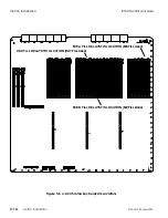
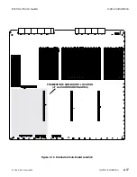
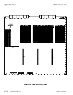
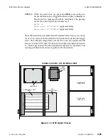
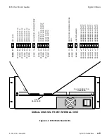
Remove the 4MB DRAM SIMM at location UW20 indicated
in Figure 3-15, on the following page, by lifting the ejector
lever all the way up. One end of the SIMM is notched. Note
the end of the socket this SIMM end was installed in.
STEP 3:
Lift the ejector lever all the way up before trying to seat the
8MB DRAM SIMM. If you do not lift the lever, it prevents you
from fully seating the SIMM in its socket.
STEP 4:
Use the Accom supplied tool to reseat the Switcher board in
the 8150 Signal Chassis.
STEP 5:
Power up the Signal Chassis. When it boots up, press the
SHOW STATUS
button. In the upper right hand System
Display box, the Memory readout should be 8MB. The 8150
can now store 100 Timeline effects in on-line memory, and
the enhanced chroma key auto setup function is now active.
8150 Technical Guide
Option Installation
9100-0212-04 - May 2000
Option Installation
3-25
Summary of Contents for ASWR8150
Page 12: ...Table of Contents 8150 Technical Guide X Contents 9100 0212 04 May 2000...
Page 39: ......
Page 80: ...Control Panel Connector Detail 8150 Technical Guide 2 40 Installation 9100 0212 04 May 2000...
Page 109: ...Option Installation 8150 Technical Guide 3 30 Option Installation 9100 0212 04 May 2000...
Page 236: ...8150 Partial Parts List 8150 Technical Guide A 6 Appendix 9100 0212 04 May 2000...

