Option Installation
Aux Bus 1, 2
Before proceeding, ensure that you have two Accom SIMM type
Delaystiks, Accom P/N 9400-0706.
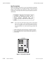
WARNING: Removing the Switcher board
disconnects the RAM battery backup. Save all
effects, timelines, personality files, and
engineering setups to disk before extracting the
board.
STEP 1:
Power down the 8150 Signal Chassis. Remove the integral
front cover/air filter to access the 8150 Switcher board. Use
the Accom supplied tool to extract the Switcher board from
the chassis and lay it on a clean, static free, grounded work
surface.
NOTE: Seating the Delaystiks requires moderate pressure.
Ensure that the Switcher board is sufficiently supported so
it does not flex.
STEP 2:
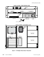
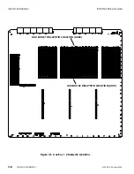
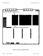
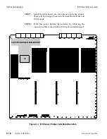
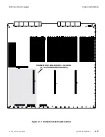
Install the Delaystiks in the SIMM sockets indicated in Figure
3-5, on the following page. Orient the Delaystiks like all the
other Delaystiks installed on the Switcher board.
Lift the ejector lever all the way up before trying to seat the
Delaystik. Otherwise, the lever prevents you from fully
seating the Delaystik.
STEP 3:
Use the Accom supplied tool to reseat the Switcher board in
the 8150 Signal Chassis.
STEP 4:
Power up the Signal Chassis. Assign a known video source
to Aux buses 1 and 2 and confirm video is present at each
output. Confirm that 1V p-p analog composite sync is present
on the Aux Ref output.
8150 Technical Guide
Option Installation
9100-0212-04 - May 2000
Option Installation
3-7
Summary of Contents for ASWR8150
Page 12: ...Table of Contents 8150 Technical Guide X Contents 9100 0212 04 May 2000...
Page 39: ......
Page 80: ...Control Panel Connector Detail 8150 Technical Guide 2 40 Installation 9100 0212 04 May 2000...
Page 109: ...Option Installation 8150 Technical Guide 3 30 Option Installation 9100 0212 04 May 2000...
Page 236: ...8150 Partial Parts List 8150 Technical Guide A 6 Appendix 9100 0212 04 May 2000...

