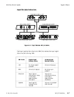
Input Module Indicators
The Input modules have dual color LEDs that indicate the input signal
status. See the following table.
LED Color
Digital Input
Module Status
Analog Input
Module Status
OFF
No input signal
present
(Does not apply)
RED
(Does not apply)
No input sync
present
YELLOW
Input signal
unlocked or does
not match
selected line
standard
Input sync
unlocked or does
not match
selected line
standard
GREEN
Input signal
present and
locked
Input sync present
and locked
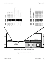
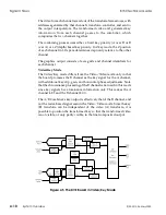
DUAL SERIAL INPUT
COMPOSITE VIDEO + KEY
DUAL COMPONENT INPUT
DUAL PARALLEL INPUT
COMPONENT VIDEO & KEY
LEDS
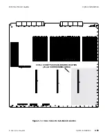
Figure 4-3 Input Module LED Locations
8150 Technical Guide
Signal Chassis
9100-0212-04 - May 2000
System Overview
4-7
Summary of Contents for ASWR8150
Page 12: ...Table of Contents 8150 Technical Guide X Contents 9100 0212 04 May 2000...
Page 39: ......
Page 80: ...Control Panel Connector Detail 8150 Technical Guide 2 40 Installation 9100 0212 04 May 2000...
Page 109: ...Option Installation 8150 Technical Guide 3 30 Option Installation 9100 0212 04 May 2000...
Page 236: ...8150 Partial Parts List 8150 Technical Guide A 6 Appendix 9100 0212 04 May 2000...

