128 Parameters
22.09
Shape time dec2
Defines the shape of the deceleration ramp at the end of the
deceleration. See parameter
0.000 … 1800.000
s
Ramp shape at end of deceleration.
1000 = 1 s
22.10
Acc time jogging
Defines the acceleration time for the jogging function i.e. the
time required for the speed to change from zero to the speed
value defined by parameter
0.000 … 1800.000
s
Acceleration time for jogging.
1000 = 1 s
22.11
Dec time jogging
Defines the deceleration time for the jogging function i.e. the
time required for the speed to change from the speed value
defined by parameter
to zero.
0.000 … 1800.000
s
Deceleration time for jogging.
1000 = 1 s
22.12
Em stop time
Defines the time inside which the drive is stopped if an
emergency stop OFF3 is activated (i.e. the time required for
the speed to change from the speed value defined by
parameter
to zero). Emergency stop
activation source is selected by parameter
. Emergency stop can also be activated through fieldbus
(
).
Note:
Emergency stop OFF1 uses the active ramp time.
0.000 … 1800.000
s
Emergency stop OFF3 deceleration time.
1000 = 1 s
23
23 Speed ctrl
Speed controller settings.
23.01
Proport gain
Defines the proportional gain (K
p
) of the speed controller. Too
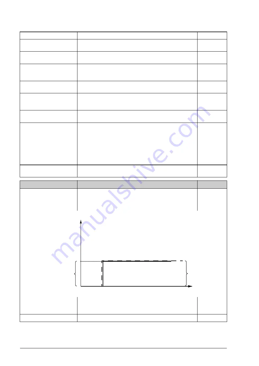
great a gain may cause speed oscillation. The figure below
shows the speed controller output after an error step when
the error remains constant.
If gain is set to 1, a 10% change in error value (reference -
actual value) causes the speed controller output to change by
10%.
0.00 … 200.00
Proportional gain for speed controller.
100 = 1
No.
Name/Value
Description
FbEq
Gain = K
p
= 1
T
I
= Integration time = 0
T
D
= Derivation time = 0
%
Controller
output = K
p
× e
Time
e = Error value
Controller output
Error value
Summary of Contents for ACS850 series
Page 1: ...ACS850 Firmware Manual ACS850 Standard Control Program...
Page 2: ......
Page 4: ......
Page 24: ...24 Start up...
Page 28: ...28 Control locations and operating modes...
Page 252: ...252 Fieldbus control...


