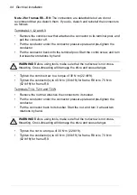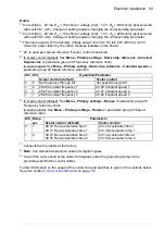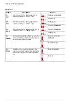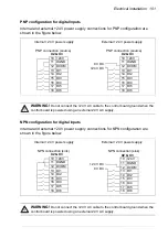
104 Electrical installation
DI6 as frequency input
If DI6 is used as a frequency input, see
ACS580 firmware manual
(3AXD50000016097 [English]) for how to set parameters accordingly.
AI1 and AI2 as Pt100, Pt1000, Ni1000, KTY83 and KTY84 sensor inputs (X1)
One, two or three Pt100 sensors; one, two or three Pt1000 sensors; or one Ni1000,
KTY83 or KTY84 sensor for motor temperature measurement can be connected
between an analog input and output as shown below. Do not connect both ends of
the cable shields directly to ground. If a capacitor cannot be used at one end, leave
that end of the shield unconnected.
WARNING!
As the inputs pictured above are not insulated according to IEC 60664, the
connection of the motor temperature sensor requires double or reinforced insulation
between motor live parts and the sensor. If the assembly does not fulfill the requirement, the I/O
board terminals must be protected against contact and must not be connected to other
equipment or the temperature sensor must be isolated from the I/O terminals.
Safe torque off (X4)
For the drive to start, both connections (+24 V DC to IN1 and +24 V DC to IN2) must
be closed. By default, the terminal block has jumpers to close the circuit. Remove the
jumpers before connecting an external Safe torque off circuitry to the drive. See
chapter
on page
.
Note:
Only 24 V DC can be used for STO. Only PNP input configuration can be used.
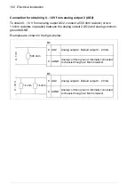
1…3 × (Pt100 or Pt1000) or
3.3 nF
> 630 V AC
AIn
AGND
AOn
AGND
1)
2)
T
T
T
1 × (Ni1000 or KTY83 or KTY84)
1) Set the input type to voltage with switch S1 for analog input AI1 or with S2 for analog input
AI2. Set the appropriate analog input unit to V (volt) in parameter group 12 Standard AI.
2) Select the excitation mode in parameter group 13 Standard AO.
Summary of Contents for ACS580-01 drives
Page 1: ...ABB general purpose drives Hardware manual ACS580 01 drives 0 75 to 250 kW...
Page 4: ......
Page 11: ...Table of contents 11 Document library on the Internet 225...
Page 12: ...12 Table of contents...
Page 72: ...72 Planning the electrical installation...
Page 79: ...Electrical installation 79 R6 R9 3 3 4...
Page 132: ...132 Maintenance and hardware diagnostics...
Page 168: ...168 Dimension drawings Frame R0 IP21 3AXD10000257110...
Page 169: ...Dimension drawings 169 Frame R0 IP55 3AXD10000341562...
Page 170: ...170 Dimension drawings Frame R1 IP21 3AXD10000257188...
Page 171: ...Dimension drawings 171 Frame R1 IP55 3AXD10000336766...
Page 172: ...172 Dimension drawings Frame R2 IP21 3AXD10000257203...
Page 173: ...Dimension drawings 173 Frame R2 IP55 3AXD10000341578...
Page 174: ...174 Dimension drawings Frame R3 IP21 3AXD10000257219...
Page 175: ...Dimension drawings 175 Frame R3 IP55 3AXD10000335424...
Page 176: ...176 Dimension drawings Frame R4 IP21 3AXD10000332430...
Page 177: ...Dimension drawings 177 Frame R4 IP55 3AXD10000427933...
Page 178: ...178 Dimension drawings Frame R5 IP21 3AXD10000412280...
Page 179: ...Dimension drawings 179 Frame R5 IP55 3AXD10000415964...
Page 180: ...180 Dimension drawings Frame R6 IP21 3AXD10000258705...
Page 181: ...Dimension drawings 181 Frame R6 IP55 3AXD10000330667...
Page 182: ...182 Dimension drawings Frame R7 IP21 3AXD10000258995...
Page 183: ...Dimension drawings 183 Frame R7 IP55 3AXD10000330932...
Page 184: ...184 Dimension drawings Frame R8 IP21 3AXD10000287670...
Page 185: ...Dimension drawings 185 Frame R8 IP55 3AXD10000332446...
Page 186: ...186 Dimension drawings Frame R9 IP21 3AXD10000287428...
Page 187: ...Dimension drawings 187 Frame R9 IP55 3AXD10000334310...
Page 188: ...188 Dimension drawings...
Page 196: ...196 Resistor braking...

