204 Safe torque off function
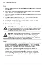
Use
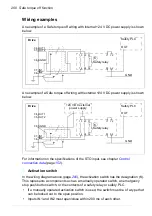
1. Open the activation switch, or activate the safety functionality that is wired to the
STO connection.
2. STO inputs on the drive control board de-energize, and the drive control board
cuts off the control voltage from the drive IGBTs.
3. The control program generates an indication as defined by parameter 31.22 STO
indication run/stop.
4. The motor coasts to a stop (if running). The drive will not restart while the
activation switch or safety relay contacts are open.
5. Deactivate the STO by closing the activation switch, or resetting the safety
functionality that is wired to the STO connection.
6. Reset any faults before restarting.
WARNING!
The Safe torque off function does not disconnect the voltage of
the main and auxiliary circuits from the drive. Therefore maintenance work
on electrical parts of the drive or the motor can only be carried out after
isolating the drive from the main supply.
WARNING!
(With permanent magnet motors only) In case of a multiple
IGBT power semiconductor failure, the drive system can produce an
alignment torque which maximally rotates the motor shaft by 180/
p
degrees (with permanent magnet motors) regardless of the activation of
the Safe torque off function.
p
denotes the number of pole pairs.
Notes
:
• If a running drive is stopped by using the Safe torque off function, the drive will cut
off the motor supply voltage and the motor will coast to a stop. If this causes
danger or is not otherwise acceptable, stop the drive and machinery using the
appropriate stop mode before activating the Safe torque off function.
• The Safe torque off function overrides all other functions of the drive unit.
• The Safe torque off function is ineffective against deliberate sabotage or misuse.
• The Safe torque off function has been designed to reduce the recognized
hazardous conditions. In spite of this, it is not always possible to eliminate all
potential hazards. The assembler of the machine must inform the final user about
the residual risks.
Summary of Contents for ACS580-01 drives
Page 1: ...ABB general purpose drives Hardware manual ACS580 01 drives 0 75 to 250 kW...
Page 4: ......
Page 11: ...Table of contents 11 Document library on the Internet 225...
Page 12: ...12 Table of contents...
Page 72: ...72 Planning the electrical installation...
Page 79: ...Electrical installation 79 R6 R9 3 3 4...
Page 132: ...132 Maintenance and hardware diagnostics...
Page 168: ...168 Dimension drawings Frame R0 IP21 3AXD10000257110...
Page 169: ...Dimension drawings 169 Frame R0 IP55 3AXD10000341562...
Page 170: ...170 Dimension drawings Frame R1 IP21 3AXD10000257188...
Page 171: ...Dimension drawings 171 Frame R1 IP55 3AXD10000336766...
Page 172: ...172 Dimension drawings Frame R2 IP21 3AXD10000257203...
Page 173: ...Dimension drawings 173 Frame R2 IP55 3AXD10000341578...
Page 174: ...174 Dimension drawings Frame R3 IP21 3AXD10000257219...
Page 175: ...Dimension drawings 175 Frame R3 IP55 3AXD10000335424...
Page 176: ...176 Dimension drawings Frame R4 IP21 3AXD10000332430...
Page 177: ...Dimension drawings 177 Frame R4 IP55 3AXD10000427933...
Page 178: ...178 Dimension drawings Frame R5 IP21 3AXD10000412280...
Page 179: ...Dimension drawings 179 Frame R5 IP55 3AXD10000415964...
Page 180: ...180 Dimension drawings Frame R6 IP21 3AXD10000258705...
Page 181: ...Dimension drawings 181 Frame R6 IP55 3AXD10000330667...
Page 182: ...182 Dimension drawings Frame R7 IP21 3AXD10000258995...
Page 183: ...Dimension drawings 183 Frame R7 IP55 3AXD10000330932...
Page 184: ...184 Dimension drawings Frame R8 IP21 3AXD10000287670...
Page 185: ...Dimension drawings 185 Frame R8 IP55 3AXD10000332446...
Page 186: ...186 Dimension drawings Frame R9 IP21 3AXD10000287428...
Page 187: ...Dimension drawings 187 Frame R9 IP55 3AXD10000334310...
Page 188: ...188 Dimension drawings...
Page 196: ...196 Resistor braking...

