Introduction to the manual 25
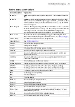
Terms and abbreviations
Term/abbreviation
Explanation
ACS-BP-S
Basic control panel, basic operator keypad for communication with the
drive
ACS-AP-x
Assistant control panel, advanced operator keypad for communication
with the drive. The ACS580 supports types ACS-AP-I, ACS-AP-S, ACS-
AP-W assistant control panel with a Bluetooth interface and ACS-BP-S
basic control panel.
Brake chopper
Conducts the surplus energy from the intermediate circuit of the drive to
the brake resistor when necessary. The chopper operates when the DC
link voltage exceeds a certain maximum limit. The voltage rise is
typically caused by deceleration (braking) of a high inertia motor.
Brake resistor
Dissipates the drive surplus braking energy conducted by the brake
chopper to heat. Essential part of the brake circuit. See
.
Control board
Circuit board in which the control program runs.
Capacitor bank
See
.
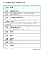
CDPI-01
Communication adapter module
CCA-01
Configuration adapter
CEIA-01
Embedded EIA-485 fieldbus adapter module
CHDI-01
Optional 115/230 V digital input extension module
CMOD-01
Optional multifunction extension module (external 24 V AC/DC and
digital I/O extension)
CMOD-02
Optional multifunction extension module (external 24 V AC/DC and
isolated PTC interface)
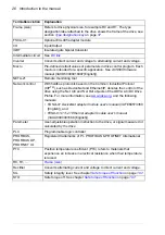
DC link
DC circuit between rectifier and inverter
DC link capacitors
Energy storage which stabilizes the intermediate circuit DC voltage
DPMP-01
Mounting platform for ACS-AP control panel (flange mounting)
DPMP-02
Mounting platform for ACS-AP control panel (surface mounting)
Drive
Frequency converter for controlling AC motors
EMC
Electromagnetic compatibility
EFB
Embedded fieldbus
FBA
Fieldbus adapter
FCAN-01
Optional CANopen adapter module
FCNA-01
ControlNet adapter module
FDNA-01
Optional DeviceNet adapter module
FECA-01
Optional EtherCAT adapter module
FENA-11/-21
Optional Ethernet adapter module for EtherNet/IP, Modbus TCP and
PROFINET IO protocols
FEPL-02
Optional Ethernet POWERLINK adapter module
FPBA-01
Optional PROFIBUS DP adapter module
Summary of Contents for ACS580-01 drives
Page 1: ...ABB general purpose drives Hardware manual ACS580 01 drives 0 75 to 250 kW...
Page 4: ......
Page 11: ...Table of contents 11 Document library on the Internet 225...
Page 12: ...12 Table of contents...
Page 72: ...72 Planning the electrical installation...
Page 79: ...Electrical installation 79 R6 R9 3 3 4...
Page 132: ...132 Maintenance and hardware diagnostics...
Page 168: ...168 Dimension drawings Frame R0 IP21 3AXD10000257110...
Page 169: ...Dimension drawings 169 Frame R0 IP55 3AXD10000341562...
Page 170: ...170 Dimension drawings Frame R1 IP21 3AXD10000257188...
Page 171: ...Dimension drawings 171 Frame R1 IP55 3AXD10000336766...
Page 172: ...172 Dimension drawings Frame R2 IP21 3AXD10000257203...
Page 173: ...Dimension drawings 173 Frame R2 IP55 3AXD10000341578...
Page 174: ...174 Dimension drawings Frame R3 IP21 3AXD10000257219...
Page 175: ...Dimension drawings 175 Frame R3 IP55 3AXD10000335424...
Page 176: ...176 Dimension drawings Frame R4 IP21 3AXD10000332430...
Page 177: ...Dimension drawings 177 Frame R4 IP55 3AXD10000427933...
Page 178: ...178 Dimension drawings Frame R5 IP21 3AXD10000412280...
Page 179: ...Dimension drawings 179 Frame R5 IP55 3AXD10000415964...
Page 180: ...180 Dimension drawings Frame R6 IP21 3AXD10000258705...
Page 181: ...Dimension drawings 181 Frame R6 IP55 3AXD10000330667...
Page 182: ...182 Dimension drawings Frame R7 IP21 3AXD10000258995...
Page 183: ...Dimension drawings 183 Frame R7 IP55 3AXD10000330932...
Page 184: ...184 Dimension drawings Frame R8 IP21 3AXD10000287670...
Page 185: ...Dimension drawings 185 Frame R8 IP55 3AXD10000332446...
Page 186: ...186 Dimension drawings Frame R9 IP21 3AXD10000287428...
Page 187: ...Dimension drawings 187 Frame R9 IP55 3AXD10000334310...
Page 188: ...188 Dimension drawings...
Page 196: ...196 Resistor braking...


