Optional I/O extension modules 213
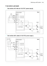
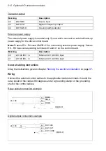
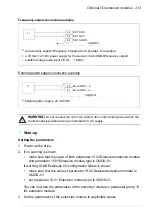
Frequency output connection example
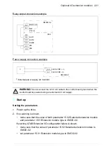
External power supply connection example
WARNING!
Do not connect the +24 V AC cable to the control board ground when the
control board is powered using an external 24 V AC supply.
Start-up
Setting the parameters
1. Power up the drive.
2. If no warning is shown,
•
make sure that the value of both parameter 15.02 Detected extension module
and parameter 15.01Extension module type is CMOD-01.
If warning A7AB Extension I/O configuration failure is shown,
•
make sure that the value of parameter 15.02 Detected extension module is
CMOD-01.
•
set parameter 15.01 Extension module type to CMOD-01.
You can now see the parameters of the extension module in parameter group 15
I/O extension module.
3. Set the parameters of the extension module to applicable values.
42
43
44
1)
1)
An externally supplied frequency indicator which provides, for example:
• a 40 mA / 12 V DC power supply for the sensor circuit (CMOD frequency output)
• suitable voltage pulse input (10 Hz … 16 kHz).
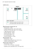
CMOD-01
DO1 SRC
DO1 OUT
DO1 SGND
40
41
1)
1)
External power supply, 24 V AC/DC
+
-
CMOD-01
24V AC/DC + in
24V AC/DC - in
Summary of Contents for ACS580-01 drives
Page 1: ...ABB general purpose drives Hardware manual ACS580 01 drives 0 75 to 250 kW...
Page 4: ......
Page 11: ...Table of contents 11 Document library on the Internet 225...
Page 12: ...12 Table of contents...
Page 72: ...72 Planning the electrical installation...
Page 79: ...Electrical installation 79 R6 R9 3 3 4...
Page 132: ...132 Maintenance and hardware diagnostics...
Page 168: ...168 Dimension drawings Frame R0 IP21 3AXD10000257110...
Page 169: ...Dimension drawings 169 Frame R0 IP55 3AXD10000341562...
Page 170: ...170 Dimension drawings Frame R1 IP21 3AXD10000257188...
Page 171: ...Dimension drawings 171 Frame R1 IP55 3AXD10000336766...
Page 172: ...172 Dimension drawings Frame R2 IP21 3AXD10000257203...
Page 173: ...Dimension drawings 173 Frame R2 IP55 3AXD10000341578...
Page 174: ...174 Dimension drawings Frame R3 IP21 3AXD10000257219...
Page 175: ...Dimension drawings 175 Frame R3 IP55 3AXD10000335424...
Page 176: ...176 Dimension drawings Frame R4 IP21 3AXD10000332430...
Page 177: ...Dimension drawings 177 Frame R4 IP55 3AXD10000427933...
Page 178: ...178 Dimension drawings Frame R5 IP21 3AXD10000412280...
Page 179: ...Dimension drawings 179 Frame R5 IP55 3AXD10000415964...
Page 180: ...180 Dimension drawings Frame R6 IP21 3AXD10000258705...
Page 181: ...Dimension drawings 181 Frame R6 IP55 3AXD10000330667...
Page 182: ...182 Dimension drawings Frame R7 IP21 3AXD10000258995...
Page 183: ...Dimension drawings 183 Frame R7 IP55 3AXD10000330932...
Page 184: ...184 Dimension drawings Frame R8 IP21 3AXD10000287670...
Page 185: ...Dimension drawings 185 Frame R8 IP55 3AXD10000332446...
Page 186: ...186 Dimension drawings Frame R9 IP21 3AXD10000287428...
Page 187: ...Dimension drawings 187 Frame R9 IP55 3AXD10000334310...
Page 188: ...188 Dimension drawings...
Page 196: ...196 Resistor braking...

