


94 Electrical installation
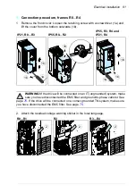
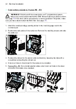
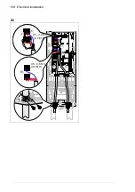
Note 2 for frames R8…R9:
The connectors are detachable but we do not
recommend that you detach them. If you do, detach and reinstall the connectors
as follows.
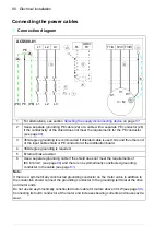
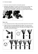
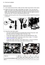
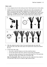
Terminals L1, L2 and L3
•
Remove the combi screw that attaches the connector to its terminal post, and
pull the connector off.
•
Put the conductor under the connector pressure plate and pre-tighten the
conductor.
•
Put the connector back onto the terminal post. Start the combi screw, and turn
it at least two rotations by hand.
WARNING!
Before using tools, make sure that the nut/screw is not cross-
threading. Cross-threading will damage the drive and cause danger.
•
Tighten the combi screw to a torque of 30 N·m (22 lbf·ft).
•
Tighten the conductor(s) to 40 N·m (30 lbf·ft) for frame R8 or to 70 N·m
(52 lbf·ft) for frame R9.
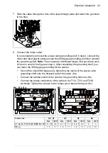
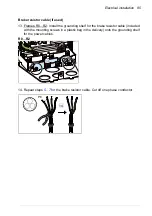
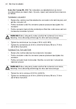
Terminals T1/U, T2/V and T3/W
•
Remove the nut that attaches the connector to its busbar.
•
Put the conductor under the connector pressure plate and pre-tighten the
conductor.
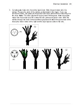
•
Put the connector back to its busbar. Start the nut, and turn it at least two
rotations by hand.
WARNING!
Before using tools, make sure that the nut/screw is not cross-
threading. Cross-threading will damage the drive and cause danger.
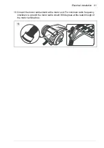
•
Tighten the nut to a torque of 30 N·m (22 lbf·ft).
•
Tighten the conductor(s) to 40 N·m (30 lbf·ft) for frame R8 or to 70 N·m
(52 lbf·ft) for frame R9.
Summary of Contents for ACS580-01 drives
Page 1: ...ABB general purpose drives Hardware manual ACS580 01 drives 0 75 to 250 kW...
Page 4: ......
Page 11: ...Table of contents 11 Document library on the Internet 225...
Page 12: ...12 Table of contents...
Page 72: ...72 Planning the electrical installation...
Page 79: ...Electrical installation 79 R6 R9 3 3 4...
Page 132: ...132 Maintenance and hardware diagnostics...
Page 168: ...168 Dimension drawings Frame R0 IP21 3AXD10000257110...
Page 169: ...Dimension drawings 169 Frame R0 IP55 3AXD10000341562...
Page 170: ...170 Dimension drawings Frame R1 IP21 3AXD10000257188...
Page 171: ...Dimension drawings 171 Frame R1 IP55 3AXD10000336766...
Page 172: ...172 Dimension drawings Frame R2 IP21 3AXD10000257203...
Page 173: ...Dimension drawings 173 Frame R2 IP55 3AXD10000341578...
Page 174: ...174 Dimension drawings Frame R3 IP21 3AXD10000257219...
Page 175: ...Dimension drawings 175 Frame R3 IP55 3AXD10000335424...
Page 176: ...176 Dimension drawings Frame R4 IP21 3AXD10000332430...
Page 177: ...Dimension drawings 177 Frame R4 IP55 3AXD10000427933...
Page 178: ...178 Dimension drawings Frame R5 IP21 3AXD10000412280...
Page 179: ...Dimension drawings 179 Frame R5 IP55 3AXD10000415964...
Page 180: ...180 Dimension drawings Frame R6 IP21 3AXD10000258705...
Page 181: ...Dimension drawings 181 Frame R6 IP55 3AXD10000330667...
Page 182: ...182 Dimension drawings Frame R7 IP21 3AXD10000258995...
Page 183: ...Dimension drawings 183 Frame R7 IP55 3AXD10000330932...
Page 184: ...184 Dimension drawings Frame R8 IP21 3AXD10000287670...
Page 185: ...Dimension drawings 185 Frame R8 IP55 3AXD10000332446...
Page 186: ...186 Dimension drawings Frame R9 IP21 3AXD10000287428...
Page 187: ...Dimension drawings 187 Frame R9 IP55 3AXD10000334310...
Page 188: ...188 Dimension drawings...
Page 196: ...196 Resistor braking...


