66 Planning the electrical installation
Implementing thermal overload and short-circuit protection
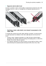
Protecting the drive and input power cable in short-circuits
Protect the drive and input cable with fuses as follows:
Size the fuses at the distribution board according to instructions given in chapter
. The fuses will protect the input cable in short-circuit
situations, restrict drive damage and prevent damage to adjoining equipment in case
of a short-circuit inside the drive.
Note:
If you want to use circuit breakers, contact the manufacturer for more
information.
Protecting the motor and motor cable in short-circuits
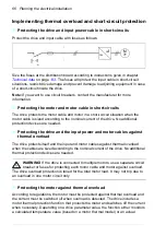
The drive protects the motor cable and motor in a short-circuit situation when the
motor cable is sized according to the nominal current of the drive. No additional
protection devices are needed.
Protecting the drive and the input power and motor cables against
thermal overload
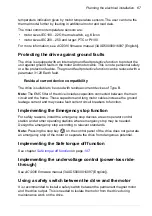
The drive protects itself and the input and motor cables against thermal overload
when the cables are sized according to the nominal current of the drive. No additional
thermal protection devices are needed.
WARNING!
If the drive is connected to multiple motors, use a separate circuit
breaker or fuses for protecting each motor cable and motor against overload.
The drive overload protection is tuned for the total motor load. It may not trip due to
an overload in one motor circuit only
Protecting the motor against thermal overload
According to regulations, the motor must be protected against thermal overload and
the current must be switched off when overload is detected. The drive includes a
motor thermal protection function that protects the motor and switches off the current
when necessary. Depending on a drive parameter value, the function either monitors
a calculated temperature value (based on a motor thermal model) or an actual
~
~
M
3~
Summary of Contents for ACS580-01 drives
Page 1: ...ABB general purpose drives Hardware manual ACS580 01 drives 0 75 to 250 kW...
Page 4: ......
Page 11: ...Table of contents 11 Document library on the Internet 225...
Page 12: ...12 Table of contents...
Page 72: ...72 Planning the electrical installation...
Page 79: ...Electrical installation 79 R6 R9 3 3 4...
Page 132: ...132 Maintenance and hardware diagnostics...
Page 168: ...168 Dimension drawings Frame R0 IP21 3AXD10000257110...
Page 169: ...Dimension drawings 169 Frame R0 IP55 3AXD10000341562...
Page 170: ...170 Dimension drawings Frame R1 IP21 3AXD10000257188...
Page 171: ...Dimension drawings 171 Frame R1 IP55 3AXD10000336766...
Page 172: ...172 Dimension drawings Frame R2 IP21 3AXD10000257203...
Page 173: ...Dimension drawings 173 Frame R2 IP55 3AXD10000341578...
Page 174: ...174 Dimension drawings Frame R3 IP21 3AXD10000257219...
Page 175: ...Dimension drawings 175 Frame R3 IP55 3AXD10000335424...
Page 176: ...176 Dimension drawings Frame R4 IP21 3AXD10000332430...
Page 177: ...Dimension drawings 177 Frame R4 IP55 3AXD10000427933...
Page 178: ...178 Dimension drawings Frame R5 IP21 3AXD10000412280...
Page 179: ...Dimension drawings 179 Frame R5 IP55 3AXD10000415964...
Page 180: ...180 Dimension drawings Frame R6 IP21 3AXD10000258705...
Page 181: ...Dimension drawings 181 Frame R6 IP55 3AXD10000330667...
Page 182: ...182 Dimension drawings Frame R7 IP21 3AXD10000258995...
Page 183: ...Dimension drawings 183 Frame R7 IP55 3AXD10000330932...
Page 184: ...184 Dimension drawings Frame R8 IP21 3AXD10000287670...
Page 185: ...Dimension drawings 185 Frame R8 IP55 3AXD10000332446...
Page 186: ...186 Dimension drawings Frame R9 IP21 3AXD10000287428...
Page 187: ...Dimension drawings 187 Frame R9 IP55 3AXD10000334310...
Page 188: ...188 Dimension drawings...
Page 196: ...196 Resistor braking...


