22 Introduction to the manual
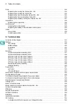
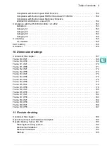
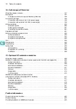
Contents of this manual
The manual consists of the following chapters:
•
(page
) gives safety instructions you must obey when
installing, commissioning, operating and servicing the drive.
•
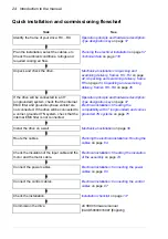
) describes applicability, target
audience, purpose and contents of this manual. It also contains a quick
installation and commissioning flowchart. At the end, it lists terms and
abbreviations.
•
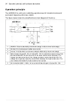
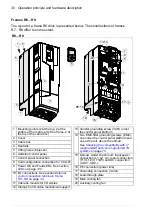
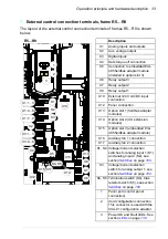
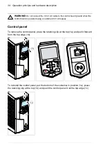
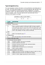
Operation principle and hardware description
) describes the operation
principle, layout, power connections and control interfaces, type designation label
and type designation information in short.
•
(page
) describes how to check the installation site,
unpack, check the delivery and install the drive mechanically.
•
Planning the electrical installation
) describes how to plan the electrical
installation of the drive, for example, how to check the compatibility of the motor
and the drive and select cables, protections and cable routing.
•
(page
) describes how to check the insulation of the
assembly and the compatibility with IT (ungrounded) and corner-grounded TN
systems. It then shows how to connect the power and control cables, install
optional modules and connect a PC.
•
(page
) contains a checklist for checking the mechanical
and electrical installation of the drive before start-up.
•
Maintenance and hardware diagnostics
) contains preventive
maintenance instructions and LED indicator descriptions.
•
) contains technical specifications of the drive, eg
ratings, sizes and technical requirements as well as provisions for fulfilling the
requirements for CE and other marks.
•
) shows dimension drawings of the drive.
•
(page
) tells how to select the brake resistor.
•
(page
) describes STO features, installation and
technical data.
•
Optional I/O extension modules
(page
) describes CMOD-01 and CMOD-02
multifunction extension modules, their installation, start-up, diagnostics and
technical data.
•
(inside of the back cover, page
) tells how to make product
and service inquiries, get information on product training, provide feedback on
manuals and find documents on the Internet.
Related documents
See
on page
(inside of the front cover).
Summary of Contents for ACS580-01 drives
Page 1: ...ABB general purpose drives Hardware manual ACS580 01 drives 0 75 to 250 kW...
Page 4: ......
Page 11: ...Table of contents 11 Document library on the Internet 225...
Page 12: ...12 Table of contents...
Page 72: ...72 Planning the electrical installation...
Page 79: ...Electrical installation 79 R6 R9 3 3 4...
Page 132: ...132 Maintenance and hardware diagnostics...
Page 168: ...168 Dimension drawings Frame R0 IP21 3AXD10000257110...
Page 169: ...Dimension drawings 169 Frame R0 IP55 3AXD10000341562...
Page 170: ...170 Dimension drawings Frame R1 IP21 3AXD10000257188...
Page 171: ...Dimension drawings 171 Frame R1 IP55 3AXD10000336766...
Page 172: ...172 Dimension drawings Frame R2 IP21 3AXD10000257203...
Page 173: ...Dimension drawings 173 Frame R2 IP55 3AXD10000341578...
Page 174: ...174 Dimension drawings Frame R3 IP21 3AXD10000257219...
Page 175: ...Dimension drawings 175 Frame R3 IP55 3AXD10000335424...
Page 176: ...176 Dimension drawings Frame R4 IP21 3AXD10000332430...
Page 177: ...Dimension drawings 177 Frame R4 IP55 3AXD10000427933...
Page 178: ...178 Dimension drawings Frame R5 IP21 3AXD10000412280...
Page 179: ...Dimension drawings 179 Frame R5 IP55 3AXD10000415964...
Page 180: ...180 Dimension drawings Frame R6 IP21 3AXD10000258705...
Page 181: ...Dimension drawings 181 Frame R6 IP55 3AXD10000330667...
Page 182: ...182 Dimension drawings Frame R7 IP21 3AXD10000258995...
Page 183: ...Dimension drawings 183 Frame R7 IP55 3AXD10000330932...
Page 184: ...184 Dimension drawings Frame R8 IP21 3AXD10000287670...
Page 185: ...Dimension drawings 185 Frame R8 IP55 3AXD10000332446...
Page 186: ...186 Dimension drawings Frame R9 IP21 3AXD10000287428...
Page 187: ...Dimension drawings 187 Frame R9 IP55 3AXD10000334310...
Page 188: ...188 Dimension drawings...
Page 196: ...196 Resistor braking...

