26 Introduction to the manual
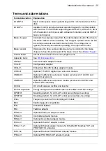
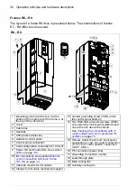
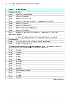
Frame (size)
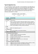
Refers to drive physical size, for example R0 and R1. The type
designation label attached to the drive shows the frame of the drive, see
section
on page
.
FSCA-01
Optional EIA-485 adapter module
I/O
Input/Output
IGBT
Insulated gate bipolar transistor
Intermediate circuit
See
.
Inverter
Converts direct current and voltage to alternating current and voltage.
Macro
Pre-defined default values of parameters in drive control program. Each
macro is intended for a specific application. See
ACS580 firmware
manual
(3AXD50000016097[English]).
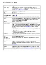
NETA-21
Remote monitoring tool
Network control
With fieldbus protocols based on the Common Industrial Protocol
(CIP
TM
), such as DeviceNet and Ethernet/IP, denotes the control of the
drive using the Net Ctrl and Net Ref objects of the ODVA AC/DC Drive
Profile. For more information, see
, and the following
manuals:
• FDNA-01 DeviceNet adapter module user’s manual
(3AFE68573360
[English]), and
•
FENA-01/-11/-21 Ethernet adapter module user’s manual
(3AUA0000093568 [English]).
Parameter
User-adjustable operation instruction to the drive, or signal measured or
calculated by the drive
PLC
Programmable logic controller
PROFIBUS,
PROFIBUS DP,
PROFINET IO
Registered trademarks of PI - PROFIBUS & PROFINET International
PTC
Positive temperature coefficient (PTC) refers to materials that
experience an increase in electrical resistance when their temperature
is raised.
R0, R1, …
Rectifier
Converts alternating current and voltage to direct current and voltage.
SIL
Safety integrity level. See chapter
.
STO
Safe torque off. See chapter
on page
.
Term/abbreviation
Explanation
Summary of Contents for ACS580-01 drives
Page 1: ...ABB general purpose drives Hardware manual ACS580 01 drives 0 75 to 250 kW...
Page 4: ......
Page 11: ...Table of contents 11 Document library on the Internet 225...
Page 12: ...12 Table of contents...
Page 72: ...72 Planning the electrical installation...
Page 79: ...Electrical installation 79 R6 R9 3 3 4...
Page 132: ...132 Maintenance and hardware diagnostics...
Page 168: ...168 Dimension drawings Frame R0 IP21 3AXD10000257110...
Page 169: ...Dimension drawings 169 Frame R0 IP55 3AXD10000341562...
Page 170: ...170 Dimension drawings Frame R1 IP21 3AXD10000257188...
Page 171: ...Dimension drawings 171 Frame R1 IP55 3AXD10000336766...
Page 172: ...172 Dimension drawings Frame R2 IP21 3AXD10000257203...
Page 173: ...Dimension drawings 173 Frame R2 IP55 3AXD10000341578...
Page 174: ...174 Dimension drawings Frame R3 IP21 3AXD10000257219...
Page 175: ...Dimension drawings 175 Frame R3 IP55 3AXD10000335424...
Page 176: ...176 Dimension drawings Frame R4 IP21 3AXD10000332430...
Page 177: ...Dimension drawings 177 Frame R4 IP55 3AXD10000427933...
Page 178: ...178 Dimension drawings Frame R5 IP21 3AXD10000412280...
Page 179: ...Dimension drawings 179 Frame R5 IP55 3AXD10000415964...
Page 180: ...180 Dimension drawings Frame R6 IP21 3AXD10000258705...
Page 181: ...Dimension drawings 181 Frame R6 IP55 3AXD10000330667...
Page 182: ...182 Dimension drawings Frame R7 IP21 3AXD10000258995...
Page 183: ...Dimension drawings 183 Frame R7 IP55 3AXD10000330932...
Page 184: ...184 Dimension drawings Frame R8 IP21 3AXD10000287670...
Page 185: ...Dimension drawings 185 Frame R8 IP55 3AXD10000332446...
Page 186: ...186 Dimension drawings Frame R9 IP21 3AXD10000287428...
Page 187: ...Dimension drawings 187 Frame R9 IP55 3AXD10000334310...
Page 188: ...188 Dimension drawings...
Page 196: ...196 Resistor braking...


