Electrical installation 105
Control cable connection procedure R0…R9
WARNING!
Obey the instructions in chapter
on page
. If
you ignore them, injury or death, or damage to the equipment can occur.
1. Stop the drive and do the steps in section
Precautions before electrical work
on
page
before you start the work.
2. Remove the front cover(s) if not already removed. See page
(R0…R3), page
(R6…R9).
Analog signals
The figures for frames R0…R2 (page
), R3 (page
), R5 (page
) and
R6…R7 (page
) show an example of connecting a cable. Make the connections
according to the macro in use.
3. Cut an adequate hole into the rubber grommet and slide the grommet onto the
cable. Slide the cable through a hole in the lead-through plate and attach the
grommet to the hole.
4. Ground the outer shield of the cable 360 degrees under the grounding clamp.
Keep the cable unstripped as close to the terminals of the control board as
possible.
Frames R4…R9: Secure the cables mechanically at the clamps below the control
board.
Ground also the pair-cable shields and grounding wire at the SCR terminal.
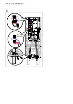
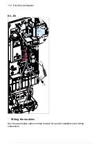
5. Route the cable as shown in the figures on pages
(R6…R9).
6. Connect the conductors to the appropriate terminals of the control board and
tighten to 0.5…0.6 N·m (0.4 lbf·ft).
Digital signals
The figures for frames R0…R2 (page
), R3 (page
), R5 (page
) and
R6…R7 (page
) show an example of connecting a cable. Make the connections
according to the macro in use.
7. Cut an adequate hole into the rubber grommet and slide the grommet onto the
cable. Slide the cable through the hole in the lead-through plate and attach the
grommet to the hole.
8. Ground the outer shield of the cable 360 degrees under the grounding clamp.
Keep the cable unstripped as close to the terminals of the control board as
possible.
Frames R5…R9: Secure the cables mechanically at the clamps below the control
board.
If you use double-shielded cables, ground also the pair-cable shields and
grounding wire at the SCR terminal.
Summary of Contents for ACS580-01 drives
Page 1: ...ABB general purpose drives Hardware manual ACS580 01 drives 0 75 to 250 kW...
Page 4: ......
Page 11: ...Table of contents 11 Document library on the Internet 225...
Page 12: ...12 Table of contents...
Page 72: ...72 Planning the electrical installation...
Page 79: ...Electrical installation 79 R6 R9 3 3 4...
Page 132: ...132 Maintenance and hardware diagnostics...
Page 168: ...168 Dimension drawings Frame R0 IP21 3AXD10000257110...
Page 169: ...Dimension drawings 169 Frame R0 IP55 3AXD10000341562...
Page 170: ...170 Dimension drawings Frame R1 IP21 3AXD10000257188...
Page 171: ...Dimension drawings 171 Frame R1 IP55 3AXD10000336766...
Page 172: ...172 Dimension drawings Frame R2 IP21 3AXD10000257203...
Page 173: ...Dimension drawings 173 Frame R2 IP55 3AXD10000341578...
Page 174: ...174 Dimension drawings Frame R3 IP21 3AXD10000257219...
Page 175: ...Dimension drawings 175 Frame R3 IP55 3AXD10000335424...
Page 176: ...176 Dimension drawings Frame R4 IP21 3AXD10000332430...
Page 177: ...Dimension drawings 177 Frame R4 IP55 3AXD10000427933...
Page 178: ...178 Dimension drawings Frame R5 IP21 3AXD10000412280...
Page 179: ...Dimension drawings 179 Frame R5 IP55 3AXD10000415964...
Page 180: ...180 Dimension drawings Frame R6 IP21 3AXD10000258705...
Page 181: ...Dimension drawings 181 Frame R6 IP55 3AXD10000330667...
Page 182: ...182 Dimension drawings Frame R7 IP21 3AXD10000258995...
Page 183: ...Dimension drawings 183 Frame R7 IP55 3AXD10000330932...
Page 184: ...184 Dimension drawings Frame R8 IP21 3AXD10000287670...
Page 185: ...Dimension drawings 185 Frame R8 IP55 3AXD10000332446...
Page 186: ...186 Dimension drawings Frame R9 IP21 3AXD10000287428...
Page 187: ...Dimension drawings 187 Frame R9 IP55 3AXD10000334310...
Page 188: ...188 Dimension drawings...
Page 196: ...196 Resistor braking...

