Electrical installation 83
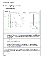
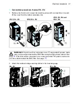
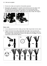
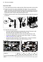
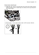
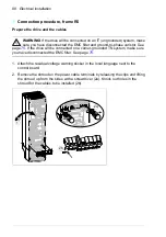
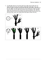
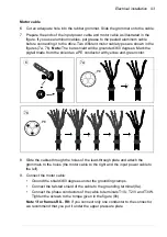
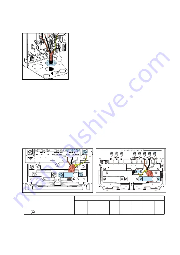
7. Slide the cable through the hole of the lead-through plate and attach the grommet
to the hole.
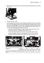
8. Connect the motor cable:
If you temporarily removed the power cable grounding shelf in step
, connect the
motor and input power cables except the 360 degree grounding, and then reinstall
the grounding shelf.
Note:
The screws are of different length; find out where each
of them is used in the figure at step
. After reinstalling the grounding shelf, you
can make the 360 degree grounding for the cables.
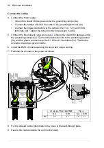
•
Ground the shield 360 degrees by tightening the clamp of the power cable
grounding shelf onto the stripped part of the cable. (8a)
•
Connect the twisted shield of the cable to the grounding terminal. (8b)
•
Connect the phase conductors of the cable to the T1/U, T2/V and T3/W
terminals. Tighten the screws to the torque given below the figure. (8c).
7
R3
8b
8c
8c
8b
R0…R2, R4
8a
8a
Frame size
R0
…
R1
R2
R3
R4
N·m
lbf·ft
N·m
lbf·ft
N·m
lbf·ft
N·m
lbf·ft
L1, L2, L3, T1/U, T2/V, T3/W, R+, R-
0.5…0.6
0.4
1.2…1.5
1.1
2.5…4.5
3.3
4
3
PE,
1.5
1.1
1.5
1.1
1.5
1.1
2.9
2.1
Summary of Contents for ACS580-01 drives
Page 1: ...ABB general purpose drives Hardware manual ACS580 01 drives 0 75 to 250 kW...
Page 4: ......
Page 11: ...Table of contents 11 Document library on the Internet 225...
Page 12: ...12 Table of contents...
Page 72: ...72 Planning the electrical installation...
Page 79: ...Electrical installation 79 R6 R9 3 3 4...
Page 132: ...132 Maintenance and hardware diagnostics...
Page 168: ...168 Dimension drawings Frame R0 IP21 3AXD10000257110...
Page 169: ...Dimension drawings 169 Frame R0 IP55 3AXD10000341562...
Page 170: ...170 Dimension drawings Frame R1 IP21 3AXD10000257188...
Page 171: ...Dimension drawings 171 Frame R1 IP55 3AXD10000336766...
Page 172: ...172 Dimension drawings Frame R2 IP21 3AXD10000257203...
Page 173: ...Dimension drawings 173 Frame R2 IP55 3AXD10000341578...
Page 174: ...174 Dimension drawings Frame R3 IP21 3AXD10000257219...
Page 175: ...Dimension drawings 175 Frame R3 IP55 3AXD10000335424...
Page 176: ...176 Dimension drawings Frame R4 IP21 3AXD10000332430...
Page 177: ...Dimension drawings 177 Frame R4 IP55 3AXD10000427933...
Page 178: ...178 Dimension drawings Frame R5 IP21 3AXD10000412280...
Page 179: ...Dimension drawings 179 Frame R5 IP55 3AXD10000415964...
Page 180: ...180 Dimension drawings Frame R6 IP21 3AXD10000258705...
Page 181: ...Dimension drawings 181 Frame R6 IP55 3AXD10000330667...
Page 182: ...182 Dimension drawings Frame R7 IP21 3AXD10000258995...
Page 183: ...Dimension drawings 183 Frame R7 IP55 3AXD10000330932...
Page 184: ...184 Dimension drawings Frame R8 IP21 3AXD10000287670...
Page 185: ...Dimension drawings 185 Frame R8 IP55 3AXD10000332446...
Page 186: ...186 Dimension drawings Frame R9 IP21 3AXD10000287428...
Page 187: ...Dimension drawings 187 Frame R9 IP55 3AXD10000334310...
Page 188: ...188 Dimension drawings...
Page 196: ...196 Resistor braking...


