Resistor braking 191
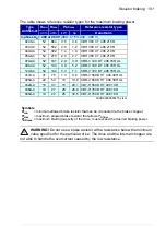
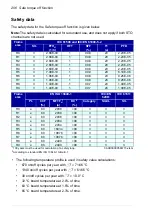
The table shows reference resistor types for the maximum braking power.
WARNING!
Do not use a brake resistor with a resistance below the minimum
value specified for the particular drive. The drive and the internal chopper are
not able to handle the overcurrent caused by the low resistance.
Type
ACS580-01
R
min
R
max
P
BRmax
Reference resistor types
ohm ohm
kW
hp
Danotherm
3-phase
U
N
= 400 or 480 V
(380…415 V, 440…480 V)
0246-4
52
864
0.6
0.8
CBH 360 C T 406 210R
03A3-4
52
582
0.9
1.2
CBH 360 C T 406 210R
04A0-4
52
392
1.4
1.9
CBH 360 C T 406 210R
05A6-4
52
279
2.0
2.7
CBH 360 C T 406 210R
07A2-4
52
191
2.9
3.9
CBR-V 330 D T 406 78R UL
09A4-4
52
140
3.9
5.2
CBR-V 330 D T 406 78R UL
12A6-4
52
104
5.3
7.1
CBR-V 330 D T 406 78R UL
017A-4
31
75
7.3
9.8
CBR-V 560 D HT 406 39R UL
025A-4
22
52
10
13.6 CBR-V 560 D HT 406 39R UL
032A-4
16
37
15
20.1 CBT-H 560 D HT 406 19R
038A-4
10
27
20
26.8 CBT-H 760 D HT 406 16R
045A-4
10
22
25
33.5 CBT-H 760 D HT 406 16R
3AXD00000586715.xls G
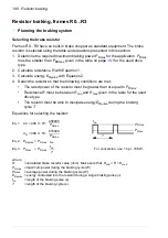
Symbols
R
min
= minimum allowed brake resistor that can be connected to the brake chopper
R
max
= maximum allowed brake resistor that allows
P
BRmax
P
BRmax
= maximum braking capacity of the drive, must exceed the desired braking power.
Summary of Contents for ACS580-01 drives
Page 1: ...ABB general purpose drives Hardware manual ACS580 01 drives 0 75 to 250 kW...
Page 4: ......
Page 11: ...Table of contents 11 Document library on the Internet 225...
Page 12: ...12 Table of contents...
Page 72: ...72 Planning the electrical installation...
Page 79: ...Electrical installation 79 R6 R9 3 3 4...
Page 132: ...132 Maintenance and hardware diagnostics...
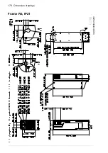
Page 168: ...168 Dimension drawings Frame R0 IP21 3AXD10000257110...
Page 169: ...Dimension drawings 169 Frame R0 IP55 3AXD10000341562...
Page 170: ...170 Dimension drawings Frame R1 IP21 3AXD10000257188...
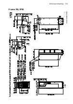
Page 171: ...Dimension drawings 171 Frame R1 IP55 3AXD10000336766...
Page 172: ...172 Dimension drawings Frame R2 IP21 3AXD10000257203...
Page 173: ...Dimension drawings 173 Frame R2 IP55 3AXD10000341578...
Page 174: ...174 Dimension drawings Frame R3 IP21 3AXD10000257219...
Page 175: ...Dimension drawings 175 Frame R3 IP55 3AXD10000335424...
Page 176: ...176 Dimension drawings Frame R4 IP21 3AXD10000332430...
Page 177: ...Dimension drawings 177 Frame R4 IP55 3AXD10000427933...
Page 178: ...178 Dimension drawings Frame R5 IP21 3AXD10000412280...
Page 179: ...Dimension drawings 179 Frame R5 IP55 3AXD10000415964...
Page 180: ...180 Dimension drawings Frame R6 IP21 3AXD10000258705...
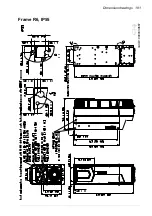
Page 181: ...Dimension drawings 181 Frame R6 IP55 3AXD10000330667...
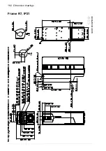
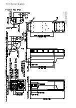
Page 182: ...182 Dimension drawings Frame R7 IP21 3AXD10000258995...
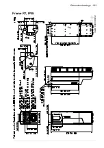
Page 183: ...Dimension drawings 183 Frame R7 IP55 3AXD10000330932...
Page 184: ...184 Dimension drawings Frame R8 IP21 3AXD10000287670...
Page 185: ...Dimension drawings 185 Frame R8 IP55 3AXD10000332446...
Page 186: ...186 Dimension drawings Frame R9 IP21 3AXD10000287428...
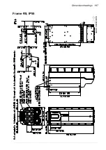
Page 187: ...Dimension drawings 187 Frame R9 IP55 3AXD10000334310...
Page 188: ...188 Dimension drawings...
Page 196: ...196 Resistor braking...


