Safe torque off function 201
Cable types and lengths
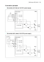
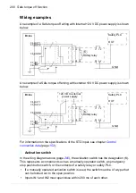
• Double-shielded twisted-pair cable is recommended.
• Maximum cable length 300 m (984 ft) between activation switch (K) and drive
control board.
Note:
A short-circuit in the wiring between the switch and an STO terminal causes a
dangerous fault and therefore it is recommended to use a safety relay (including
wiring diagnostics), or a wiring method (shield grounding, channel separation) which
reduces or eliminates the risk caused by the short-circuit.
Note:
The voltage at the INx terminals of each drive must be at least 13 V DC to be
interpreted as “1”. Pulse tolerance of input channels is 1 ms.
Grounding of protective shields
• Ground the shield in the cabling between the activation switch and the control
board at the control board.
• Ground the shield in the cabling between two control boards at one control board
only.
Operation principle
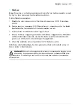
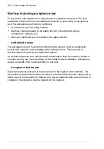
1. The Safe torque off activates (the activation switch is opened, or safety relay
contacts open).
2. The STO inputs IN1 and IN2 on the drive control board de-energize.
3. The STO cuts off the control voltage from the drive IGBTs.
4. The control program generates an indication as defined by parameter 31.22 STO
indication run/stop.
The parameter selects which indications are given when one or both Safe torque
off (STO) signals are switched off or lost. The indications also depend on whether
the drive is running or stopped when this occurs.
Note:
This parameter does not affect the operation of the STO function itself. The
STO function will operate regardless of the setting of this parameter: a running
drive will stop upon removal of one or both STO signals, and will not start until
both STO signals are restored and all faults reset.
Note:
The loss of only one STO signal always generates a fault as it is interpreted
as a malfunction of STO hardware or wiring.
5. Motor coasts to a stop (if running). The drive cannot restart while the activation
switch or safety relay contacts are open. After the contacts close, a new start
command is required to start the drive.
Summary of Contents for ACS580-01 drives
Page 1: ...ABB general purpose drives Hardware manual ACS580 01 drives 0 75 to 250 kW...
Page 4: ......
Page 11: ...Table of contents 11 Document library on the Internet 225...
Page 12: ...12 Table of contents...
Page 72: ...72 Planning the electrical installation...
Page 79: ...Electrical installation 79 R6 R9 3 3 4...
Page 132: ...132 Maintenance and hardware diagnostics...
Page 168: ...168 Dimension drawings Frame R0 IP21 3AXD10000257110...
Page 169: ...Dimension drawings 169 Frame R0 IP55 3AXD10000341562...
Page 170: ...170 Dimension drawings Frame R1 IP21 3AXD10000257188...
Page 171: ...Dimension drawings 171 Frame R1 IP55 3AXD10000336766...
Page 172: ...172 Dimension drawings Frame R2 IP21 3AXD10000257203...
Page 173: ...Dimension drawings 173 Frame R2 IP55 3AXD10000341578...
Page 174: ...174 Dimension drawings Frame R3 IP21 3AXD10000257219...
Page 175: ...Dimension drawings 175 Frame R3 IP55 3AXD10000335424...
Page 176: ...176 Dimension drawings Frame R4 IP21 3AXD10000332430...
Page 177: ...Dimension drawings 177 Frame R4 IP55 3AXD10000427933...
Page 178: ...178 Dimension drawings Frame R5 IP21 3AXD10000412280...
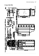
Page 179: ...Dimension drawings 179 Frame R5 IP55 3AXD10000415964...
Page 180: ...180 Dimension drawings Frame R6 IP21 3AXD10000258705...
Page 181: ...Dimension drawings 181 Frame R6 IP55 3AXD10000330667...
Page 182: ...182 Dimension drawings Frame R7 IP21 3AXD10000258995...
Page 183: ...Dimension drawings 183 Frame R7 IP55 3AXD10000330932...
Page 184: ...184 Dimension drawings Frame R8 IP21 3AXD10000287670...
Page 185: ...Dimension drawings 185 Frame R8 IP55 3AXD10000332446...
Page 186: ...186 Dimension drawings Frame R9 IP21 3AXD10000287428...
Page 187: ...Dimension drawings 187 Frame R9 IP55 3AXD10000334310...
Page 188: ...188 Dimension drawings...
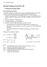
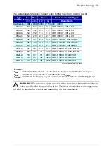
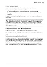
Page 196: ...196 Resistor braking...

