110 Electrical installation
Installing option modules
Note:
If you will install the FPBA
-
01 module, see section
on page
for suitable connector types.
Mechanical installation of option modules
See section
Overview of power and control connections
page
for the available
slots for each module. Install the option modules as follows:
WARNING!
Obey the instructions in chapter
on page
you ignore them, injury or death, or damage to the equipment can occur.
Note:
Slot 2 in frames R0…R4 is at
U
DC
potential. You must disconnect power
supplies before installing or removing an I/O extension module.
Stop the drive and do the steps in section
Precautions before electrical work
on page
before you start the work.
1. Remove the front cover(s) if not already removed. See page
(R0…R4), page
(R5) or page
The figures for frames R0…R4 (page
) show an example
of installing option modules.
Option slot 3 (embedded fieldbus adapter modules)
2. The drive is delivered with the standard embedded fieldbus adapter module
CEIA-01 installed.
If you have ordered another option module, remove the CEIA
-
01 module by
carefully bending the retaining clips to the sides while pulling the module outward,
and put the other module carefully into its position.
Note:
Frames R0…R4: The module in option slot 3 is under the module in option slot
1. If you have to change the module in option slot 3, remove first the any module in
option slot 1, if present.
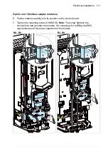
Option slot 2 (I/O extension modules)
3. Put the module carefully into its position on the control board.
4. Tighten the mounting screw.
5. Tighten the grounding screw (CHASSIS).
Note:
The screw grounds the module. It
is necessary for fulfilling the EMC requirements and for proper operation of the
module.
Note:
Frames R0…R2:
The module in option slot 2 covers the power terminals. Do
not install a module in option slot 2 before you have installed the power cables.
Summary of Contents for ACS580-01 drives
Page 1: ...ABB general purpose drives Hardware manual ACS580 01 drives 0 75 to 250 kW...
Page 4: ......
Page 11: ...Table of contents 11 Document library on the Internet 225...
Page 12: ...12 Table of contents...
Page 72: ...72 Planning the electrical installation...
Page 79: ...Electrical installation 79 R6 R9 3 3 4...
Page 132: ...132 Maintenance and hardware diagnostics...
Page 168: ...168 Dimension drawings Frame R0 IP21 3AXD10000257110...
Page 169: ...Dimension drawings 169 Frame R0 IP55 3AXD10000341562...
Page 170: ...170 Dimension drawings Frame R1 IP21 3AXD10000257188...
Page 171: ...Dimension drawings 171 Frame R1 IP55 3AXD10000336766...
Page 172: ...172 Dimension drawings Frame R2 IP21 3AXD10000257203...
Page 173: ...Dimension drawings 173 Frame R2 IP55 3AXD10000341578...
Page 174: ...174 Dimension drawings Frame R3 IP21 3AXD10000257219...
Page 175: ...Dimension drawings 175 Frame R3 IP55 3AXD10000335424...
Page 176: ...176 Dimension drawings Frame R4 IP21 3AXD10000332430...
Page 177: ...Dimension drawings 177 Frame R4 IP55 3AXD10000427933...
Page 178: ...178 Dimension drawings Frame R5 IP21 3AXD10000412280...
Page 179: ...Dimension drawings 179 Frame R5 IP55 3AXD10000415964...
Page 180: ...180 Dimension drawings Frame R6 IP21 3AXD10000258705...
Page 181: ...Dimension drawings 181 Frame R6 IP55 3AXD10000330667...
Page 182: ...182 Dimension drawings Frame R7 IP21 3AXD10000258995...
Page 183: ...Dimension drawings 183 Frame R7 IP55 3AXD10000330932...
Page 184: ...184 Dimension drawings Frame R8 IP21 3AXD10000287670...
Page 185: ...Dimension drawings 185 Frame R8 IP55 3AXD10000332446...
Page 186: ...186 Dimension drawings Frame R9 IP21 3AXD10000287428...
Page 187: ...Dimension drawings 187 Frame R9 IP55 3AXD10000334310...
Page 188: ...188 Dimension drawings...
Page 196: ...196 Resistor braking...


