Maintenance and hardware diagnostics 121
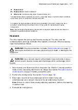
Heatsink
The drive heatsink fins pick up dust from the cooling air. The drive runs into
overtemperature warnings and faults if the heatsink is not clean. When necessary,
clean the heatsink as follows.
WARNING!
Obey the instructions in chapter
on page
Ignoring the instructions can cause physical injury or death, or damage to the
equipment.
WARNING!
Use a vacuum cleaner with antistatic hose and nozzle. Using a
normal vacuum cleaner creates static discharges which can damage circuit
boards.
1. Stop the drive and disconnect it from the power line. Wait for 5 minutes and then
make sure by measuring that there is no voltage. See section
before you start the work.
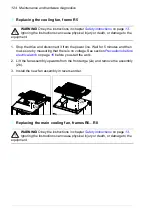
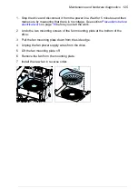
2. Remove the cooling fan(s). See section
on page
.
3. Blow clean, dry and oil free compressed air from bottom to top and
simultaneously use a vacuum cleaner at the air outlet to trap the dust.
Note:
If there is a risk of dust entering adjoining equipment, perform the cleaning
in another room.
4. Reinstall the cooling fan(s).
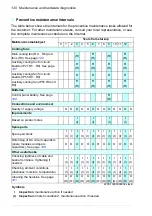
R
Replacement
(R) Replacement
in harsh conditions*
O
Other work
(commissioning, tests, measurements, etc.)
* Ambient temperature constantly over 40 °C, especially dusty or humid ambient conditions,
cyclic heavy load, or continuous nominal (full) load.
To maintain the best possible performance and reliability of the drive, inspect the drive
annually. Contact the service at least once in three years for replacement of aging
components.
Note:
Recommended maintenance intervals and component replacements are based on
operation in specified ambient conditions.
Summary of Contents for ACS580-01 drives
Page 1: ...ABB general purpose drives Hardware manual ACS580 01 drives 0 75 to 250 kW...
Page 4: ......
Page 11: ...Table of contents 11 Document library on the Internet 225...
Page 12: ...12 Table of contents...
Page 72: ...72 Planning the electrical installation...
Page 79: ...Electrical installation 79 R6 R9 3 3 4...
Page 132: ...132 Maintenance and hardware diagnostics...
Page 168: ...168 Dimension drawings Frame R0 IP21 3AXD10000257110...
Page 169: ...Dimension drawings 169 Frame R0 IP55 3AXD10000341562...
Page 170: ...170 Dimension drawings Frame R1 IP21 3AXD10000257188...
Page 171: ...Dimension drawings 171 Frame R1 IP55 3AXD10000336766...
Page 172: ...172 Dimension drawings Frame R2 IP21 3AXD10000257203...
Page 173: ...Dimension drawings 173 Frame R2 IP55 3AXD10000341578...
Page 174: ...174 Dimension drawings Frame R3 IP21 3AXD10000257219...
Page 175: ...Dimension drawings 175 Frame R3 IP55 3AXD10000335424...
Page 176: ...176 Dimension drawings Frame R4 IP21 3AXD10000332430...
Page 177: ...Dimension drawings 177 Frame R4 IP55 3AXD10000427933...
Page 178: ...178 Dimension drawings Frame R5 IP21 3AXD10000412280...
Page 179: ...Dimension drawings 179 Frame R5 IP55 3AXD10000415964...
Page 180: ...180 Dimension drawings Frame R6 IP21 3AXD10000258705...
Page 181: ...Dimension drawings 181 Frame R6 IP55 3AXD10000330667...
Page 182: ...182 Dimension drawings Frame R7 IP21 3AXD10000258995...
Page 183: ...Dimension drawings 183 Frame R7 IP55 3AXD10000330932...
Page 184: ...184 Dimension drawings Frame R8 IP21 3AXD10000287670...
Page 185: ...Dimension drawings 185 Frame R8 IP55 3AXD10000332446...
Page 186: ...186 Dimension drawings Frame R9 IP21 3AXD10000287428...
Page 187: ...Dimension drawings 187 Frame R9 IP55 3AXD10000334310...
Page 188: ...188 Dimension drawings...
Page 196: ...196 Resistor braking...


