Optional I/O extension modules 217
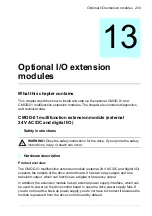
CMOD-02 multifunction extension module
(external 24 V AC/DC and isolated PTC interface)
Safety instructions
WARNING!
Obey the safety instructions for the drive. If you ignore the safety
instructions, injury or death can occur.
Hardware description
Product overview
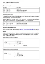
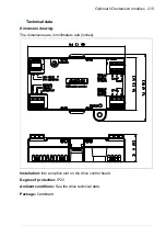
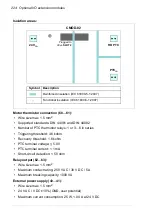
The CMOD-02 multifunction extension module (external 24 V AC/DC and isolated
PTC interface) has a motor thermistor connection for supervising the motor
temperature and one relay output, which indicates the thermistor status. To trip the
drive, the user must connect this overtemperature indication back to the drive, for
example, to its Safe torque off input.
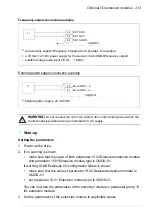
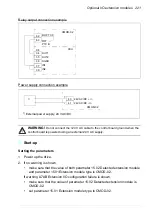
In addition, the extension module has an external power supply interface, which can
be used to power up the drive control board in case the drive power supply fails. If
you do not need the back-up power supply, you do not have to connect it because the
module is powered from the drive control board by default.
There is reinforced insulation between the motor thermistor connection, the relay
output and the drive control board interface. Thus, you can connect a motor
thermistor to the drive through the extension module.
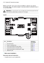
Note:
In frames R5…R9, you do not need a CMOD-02 module to use external
24 V AC/DC supply. The external supply is connected directly to terminals 40 and 41
on the control board.
WARNING!
Do not connect the +24 V AC cable to the control board ground when the
control board is powered using an external 24 V AC supply.
Summary of Contents for ACS580-01 drives
Page 1: ...ABB general purpose drives Hardware manual ACS580 01 drives 0 75 to 250 kW...
Page 4: ......
Page 11: ...Table of contents 11 Document library on the Internet 225...
Page 12: ...12 Table of contents...
Page 72: ...72 Planning the electrical installation...
Page 79: ...Electrical installation 79 R6 R9 3 3 4...
Page 132: ...132 Maintenance and hardware diagnostics...
Page 168: ...168 Dimension drawings Frame R0 IP21 3AXD10000257110...
Page 169: ...Dimension drawings 169 Frame R0 IP55 3AXD10000341562...
Page 170: ...170 Dimension drawings Frame R1 IP21 3AXD10000257188...
Page 171: ...Dimension drawings 171 Frame R1 IP55 3AXD10000336766...
Page 172: ...172 Dimension drawings Frame R2 IP21 3AXD10000257203...
Page 173: ...Dimension drawings 173 Frame R2 IP55 3AXD10000341578...
Page 174: ...174 Dimension drawings Frame R3 IP21 3AXD10000257219...
Page 175: ...Dimension drawings 175 Frame R3 IP55 3AXD10000335424...
Page 176: ...176 Dimension drawings Frame R4 IP21 3AXD10000332430...
Page 177: ...Dimension drawings 177 Frame R4 IP55 3AXD10000427933...
Page 178: ...178 Dimension drawings Frame R5 IP21 3AXD10000412280...
Page 179: ...Dimension drawings 179 Frame R5 IP55 3AXD10000415964...
Page 180: ...180 Dimension drawings Frame R6 IP21 3AXD10000258705...
Page 181: ...Dimension drawings 181 Frame R6 IP55 3AXD10000330667...
Page 182: ...182 Dimension drawings Frame R7 IP21 3AXD10000258995...
Page 183: ...Dimension drawings 183 Frame R7 IP55 3AXD10000330932...
Page 184: ...184 Dimension drawings Frame R8 IP21 3AXD10000287670...
Page 185: ...Dimension drawings 185 Frame R8 IP55 3AXD10000332446...
Page 186: ...186 Dimension drawings Frame R9 IP21 3AXD10000287428...
Page 187: ...Dimension drawings 187 Frame R9 IP55 3AXD10000334310...
Page 188: ...188 Dimension drawings...
Page 196: ...196 Resistor braking...


