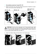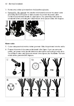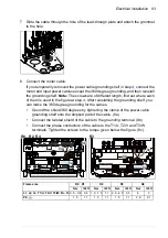
68 Planning the electrical installation
Using a contactor between the drive and the motor
Implementing the control of the output contactor depends on how you select the drive
to operate. See also section
Implementing a bypass connection
on page
When you have selected to use
• Vector control mode and motor ramp stop,
open the contactor as follows:
1. Give a stop command to the drive.
1. Wait until the drive decelerates the motor to zero speed.
2. Open the contactor.
When you have selected to use
• Vector control mode and motor coast stop; or scalar control mode,
open the contactor as follows:
1. Give a stop command to the drive.
2. Open the contactor.
WARNING!
When the Vector control mode is in use, never open the output
contactor while the drive controls the motor. The vector control operate
extremely fast, much faster than it takes for the contactor to open its contacts. When
the contactor starts opening while the drive controls the motor, the vector control will
try to maintain the load current by immediately increasing the drive output voltage to
the maximum. This will damage, or even burn the contactor completely.
Implementing a bypass connection
If frequent bypassing is required, employ mechanically or electrically interlocked
contactors between the motor and the drive and between the motor and the power
line. Make sure with interlocking that the contactors cannot be closed simultaneously.
Note:
The bypass connection cannot be used with permanent magnet motors or
synchronous reluctance motors.
WARNING!
Never connect the drive output to the electrical power network.
The connection may damage the drive.
Summary of Contents for ACS580-01 drives
Page 1: ...ABB general purpose drives Hardware manual ACS580 01 drives 0 75 to 250 kW...
Page 4: ......
Page 11: ...Table of contents 11 Document library on the Internet 225...
Page 12: ...12 Table of contents...
Page 72: ...72 Planning the electrical installation...
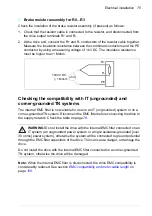
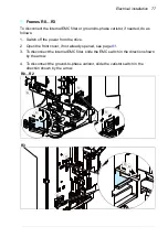
Page 79: ...Electrical installation 79 R6 R9 3 3 4...
Page 132: ...132 Maintenance and hardware diagnostics...
Page 168: ...168 Dimension drawings Frame R0 IP21 3AXD10000257110...
Page 169: ...Dimension drawings 169 Frame R0 IP55 3AXD10000341562...
Page 170: ...170 Dimension drawings Frame R1 IP21 3AXD10000257188...
Page 171: ...Dimension drawings 171 Frame R1 IP55 3AXD10000336766...
Page 172: ...172 Dimension drawings Frame R2 IP21 3AXD10000257203...
Page 173: ...Dimension drawings 173 Frame R2 IP55 3AXD10000341578...
Page 174: ...174 Dimension drawings Frame R3 IP21 3AXD10000257219...
Page 175: ...Dimension drawings 175 Frame R3 IP55 3AXD10000335424...
Page 176: ...176 Dimension drawings Frame R4 IP21 3AXD10000332430...
Page 177: ...Dimension drawings 177 Frame R4 IP55 3AXD10000427933...
Page 178: ...178 Dimension drawings Frame R5 IP21 3AXD10000412280...
Page 179: ...Dimension drawings 179 Frame R5 IP55 3AXD10000415964...
Page 180: ...180 Dimension drawings Frame R6 IP21 3AXD10000258705...
Page 181: ...Dimension drawings 181 Frame R6 IP55 3AXD10000330667...
Page 182: ...182 Dimension drawings Frame R7 IP21 3AXD10000258995...
Page 183: ...Dimension drawings 183 Frame R7 IP55 3AXD10000330932...
Page 184: ...184 Dimension drawings Frame R8 IP21 3AXD10000287670...
Page 185: ...Dimension drawings 185 Frame R8 IP55 3AXD10000332446...
Page 186: ...186 Dimension drawings Frame R9 IP21 3AXD10000287428...
Page 187: ...Dimension drawings 187 Frame R9 IP55 3AXD10000334310...
Page 188: ...188 Dimension drawings...
Page 196: ...196 Resistor braking...

