Virginia Controls, LLC
MH-3000 User Manual, 1_03C10-VC
Page 59
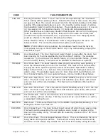
CODE
FAULT DESCRIPTION
RED-RUN or
RED2RUN
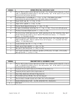
Redundancy Fault in the running or leveling circuits.
Controllers using the MH5 printed circuit board
–
The Door Contact Bypass circuit
monitoring point (LV) was energized when it should not have been, OR the Soft
Start Run signal (UTS, if used) was still on after the car stopped, OR the Pump run
input (RUN) was still off after the car stopped. Check the external circuits for
stuck relays (UL, DL, DZ, LV, LVX, STR, RU) or a stuck input.
Controllers using the MH4 printed circuit board or separate relays
–
The Run input
(RUN) did not match the Up or Down Level inputs and/or the Run input was still
on after the car has stopped. Check the external circuits for stuck relays (UL, DL,
STR, RU) or a stuck input.
Cycle the power to reset the fault.
NOTE
: If 2010 ANSI Code is enabled, and the
setting to require manual resets on Redundancy Fault is enabled, then shutdown
faults must be reset by momentarily turning on the CPU DIP Switch #4, or by
momentarily jumping the Fault Reset Input.
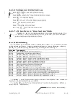
NOTE: The Fault Log Status Signals for this redundancy fault are
custom, to help determine the cause of the fault. Refer to the
section that describes the Fault Log Status Signals for a description
of the signals.
This fault can be disabled by turning on Switch 3 on the CPU Slide Switch S2. This
also turns on the Fire Buzzer output, as a reminder to turn off the defeat.
RED-SAF or
RED3SAF
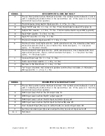
Redundancy Fault in the Safety Circuit. The condition of the Door Fault Monitor
input (DFM) was not correct, OR the Car Gate Input (5) or Door Contacts Input
(5X) was not correct. This may be caused by temporary jumpers added during
initial installation, or a short in the Safety Circuit. Check the Safety Circuit for
jumpers, or short circuits. Cycle the power to reset the fault.
NOTE
: If 2010 ANSI
Code is enabled, and the setting to require manual resets on Redundancy Fault is
enabled, then shutdown faults must be reset by momentarily turning on the CPU
DIP Switch #4, or by momentarily jumping the Fault Reset Input.
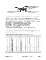
NOTE: The Fault Log Status Signals for this redundancy fault are
custom, to help determine the cause of the fault. Refer to the
section that describes the Fault Log Status Signals for a description
of the signals.
This fault can be disabled by turning on Switch 3 on the CPU Slide Switch S2. This
also turns on the Fire Buzzer output, as a reminder to turn off the defeat.


