Virginia Controls, LLC
MH-3000 User Manual, 1_03C10-VC
Page 26
5.
Hardware Description
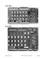
The controller consists of the Microprocessor system, Power Supply section, and Relay
Interface.
The Microprocessor system consists of the Central Processor Board (CPU), which has the
microprocessor central processing unit, the EPROM memory chip, and the appropriate
hardware to communicate to the LCD display, Keypad, and Input/Output boards.
The program is in EPROM (Electrically Programmable Read Only Memory). The floor
position and fire service functions are maintained in battery backed RAM memory. The floor
position may need to be reset when the controller is initially installed.
The Power Supply section includes the required transformers and fuses to power the
Microprocessor system and the Relay Interface.
The Relay Interface includes the required relays and contactors to interface the field
signals and devices to the microprocessor. This usually includes a printed circuit board for
normal signals, as well as other relays or contactors for signals required for each specific
job.
5.1
Transformers
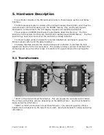
“CCXF” is the Control Circuit Transformer. This will provide the controller with 115VAC.
The primary connections will vary depending on the Building Power. See the schematic for
sizing and wiring information.
“DOXF” or “DXF” are the Door Circuit Transformer(s). The size and quantity of these
transformers will depend on the type of doors used. See the schematic for sizing and wiring
information.

