Virginia Controls, LLC
MH-3000 User Manual, 1_03C10-VC
Page 35
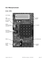
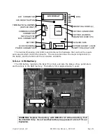
WARNING: Orient the battery properly in the battery holder. The
positive side of the battery is marked on the battery, and faces
towards the power connector and away from the EPROM socket.
WARNING: Do not use a metal (or conducting) device to remove or
install the battery.
To replace the battery, remove the old battery by gently pushing the top of the battery
towards the EPROM socket, until it is clear of the black housing, and then slide it out of the
socket. Insert the new battery by sliding the edge under the metal retaining finger, then
aligning it in the black housing. Be careful not to short out the battery. Dispose of the old
battery properly
–
do NOT incinerate the battery.
5.5.1.2
LED Description
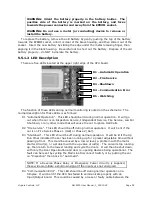
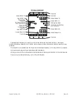
There are five LEDs located at the upper right edge of the CPU board.
The function of these LEDs during normal monitoring is noted on the schematic. The
normal description for these LEDs is as follows:
D1 "Automatic Operation". This LED should be lit during normal operation. It will go
out when the car is on Inspection Service, Independent Service, Fire Service, Low Oil
Shutdown, or any other mode that will cause the car to ignore Hall Calls.
D2 "Fire Service". This LED should be off during normal operation. It will be lit if the
car is on Fire Service Phase 1 (Hall) or Phase 2 (Car).
D3 "Shutdown". This LED should be off during normal operation. It will be lit if the Up
Run timer indicated the car has been running up for a preset adjustable time without
passing a floor. This could be caused by a low oil level; a problem with the motor
starter circuit(s); or a problem with the up valve circuit(s). The car will stop running
up, then return to the lowest landing and cycle the doors. It will then be shut down,
with only the Door Open Button and door re-opening devices being operational. The
fault can be reset by cycling the Main Line Disconnect Switch, or by putting the car
on "Inspection" then back to "Automatic".
NOTE: If a Reverse Phase Relay or Emergency Power circuitry is supplied,
these will also initiate a shutdown signal if the inputs are not energized.
D4
“Communication Error”. This LED
should be off during normal operation on a
Simplex. It will be lit if the CPU has failed to communicate properly with an
Input/Output board. This could be caused by a loose or faulty cable between the
D1
–
Automatic Operation
D2
–
Fire Service
D3 - Shutdown
D4
–
Communication Error
D5 - Watchdog

