Virginia Controls, LLC
MH-3000 User Manual, 1_03C10-VC
Page 30
5.4.3
Phase Monitor
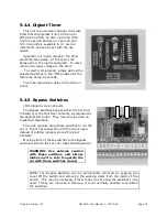
The unit provides protection for the pump
motor by continuously measuring the voltage
of each of the three phases using a
microcomputer circuit designed to sense under
and over voltage, voltage unbalance, phase
loss and phase reversal.
A trip delay is provided to prevent nuisance
tripping.
A restart delay is provided to prevent short
cycling after a momentary power outage.
Upon application of line voltage, the restart
delay begins. The output relay is de-
energized during restart delay and the LED
flashes green.
Under normal conditions, the output
energizes and the LED glows green after the
restart delay.
Under voltage, over voltage and voltage
unbalance must be sensed for a continuous trip delay period before the output is de-
energized. The output will not de-energize if the fault is corrected during the trip delay.
The LED flashes red during the trip delay, then glows red when the output is de-energized.
The restart delay begins as soon as the output relay de-energizes. If the restart delay is
completed when the fault is corrected, the output relay will energize immediately.
The output relay will not energize if a fault or phase reversal is sensed as the three phase
voltage is applied. The LED alternately flashes green then red if a phase reversal is sensed.
Reset is automatic upon correction of a fault.
The technical characteristics of the phase monitor can be determined from the part
number as follows:
Example:
TVM 460A 10 0.5S 3S
Restart Delay
Trip Delay
Voltage Unbalance %
Line Voltage
Series


