Virginia Controls, LLC
MH-3000 User Manual, 1_03C10-VC
Page 43
5.5.2.3
Input/Output LEDs
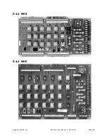
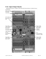
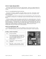
Each Input and Output point has its own LED indicator. These are located towards the
center of the board, and are on the low voltage/CPU side of the optical isolator in the I/O
circuitry.
5.5.2.3.1
Input/Output Naming Conventions
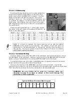
Each Input or Output is mapped to a specific address in the CPU. The address of each
Input/Output point is based both on the address of the board and on the location of the
point on the board.
The address of each I/O point is determined by the Board Address (1 through 8) and the
Point Number (1 through 16). This address is used in the Monitor I/O Menu to show the I/O
status.
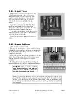
The Board Address is set by the Address Switch Block S1, as described above. The point
number is 1 to 8 starting from the left, for the top group, and 9-16 starting from the left, for
the bottom group. The point numbers are silk-screened on the board adjacent to the actual
LEDs for each point. The LEDs h
ave a “D” number silk
-screened next to the LED. This is a
component identifier, and does not correspond to their address. The address number is the
slightly larger number between the LED and its resistor. Each LED point number
corresponds to the point number by the terminal blocks.
5.5.2.4
Board Status LED
The Status LED located next to the I/O COMM IN connector shows the status of the
board. It will flash regularly, and the number of flashes indicates its mode of operation.
Flashes Mode of Operation
One
Normal operation
Two
Communication Failure. The board is
not communicating with the CPU. This
could be because the CPU is in Setup
Mode, or a cable is defective or
disconnected.
Three
Bad Address. Check the Address
Switches.
Four
Bad Data. Check the cables. Noise is
probably being induced in the wiring.

