Virginia Controls, LLC
MH-3000 User Manual, 1_03C10-VC
Page 81
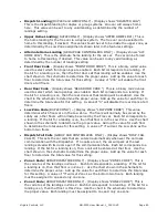
•
Zone 3 Code
(GROUP DISPATCHER ONLY) - (Display shows "ZONE 3 CODE") This is
the code to set the landings in Zone 3. Each bit corresponds to a landing. If the bit for
a landing is on, then that floor is this Zone. Use the chart in the schematic to determine
the proper value. Each landing must be assigned to one and only one zone.
•
Zone 4 Code
(GROUP DISPATCHER ONLY) - (Display shows "ZONE 4 CODE") This is
the code to set the landings in Zone 4. Each bit corresponds to a landing. If the bit for
a landing is on, then that floor is this Zone. Use the chart in the schematic to determine
the proper value. Each landing must be assigned to one and only one zone.
•
Number of Hall Calls to Initiate Heavy Program
(GROUP DISPATCHER ONLY) -
(Display shows "# CALLS = HEAVY") This is the number of Hall Calls that must be
entered to initiate the Heavy Traffic Program. This will affect the assignment of calls and
the homing scheme. See the section on Zoned Group Operation for a more complete
description of the traffic programs.
•
Number of Hall Calls to Initiate Down Heavy Program
(GROUP DISPATCHER ONLY)
- (Display shows "# CALLS=DN HEAVY") When the number of Down Hall Calls minus
the number of Up Hall Calls exceeds this value then the Down Heavy Traffic Program is
initiated. This will affect the assignment of calls and the homing scheme. See the
section on Zoned Group Operation for a more complete description of the traffic
programs.
•
Number of Car Calls to Initiate Up Heavy Program
(GROUP DISPATCHER ONLY) -
(Display shows "#CAR CALLS=UPHVY") This is the number of Car Calls that must be
entered as a car leaves the lower landings to initiate the Up Heavy Traffic Program. This
will affect the assignment of calls and the homing scheme. See the section on Zoned
Group Operation for a more complete description of the traffic programs.
6.2.5.3
Bit Features
The Bit Features are multiple features combined into several settings. Each setting
consists of 8 features that can be turned on or off individually. Refer to the sheet MH-3000
Settings in the schematic for a breakdown of each setting. A description of the standard
features that may be part of the Bit Features are listed in a following section, after the
standard settings.
•
Bit Features # 1
- (Display shows "BIT FEATURES # 1") This is a binary coded value
used to select various features as shown in the chart in the schematic on the MH-3000
SETTINGS sheet. Each bit corresponds to a different feature. If the bit for a feature is
on, then that feature is enabled. Use the chart shonw in the schematic to determine the
proper value. Add up the value for all the features that should be enabled to determine
the total value for this setting.
•
Bit Features # 2
- (Display shows "BIT FEATURES # 2") Similar to Bit Features #1.
•
Bit Features # 3
- (Display shows "BIT FEATURES # 3") Similar to Bit Features #1.
•
Bit Features # 4
- (Display shows "BIT FEATURES # 4") Similar to Bit Features #1.
•
Bit Features # 5
- (Display shows "BIT FEATURES # 5") Similar to Bit Features #1.
•
Bit Features # 6
- (Display shows "BIT FEATURES # 6") Similar to Bit Features #1.
•
Bit Features # 7
- (Display shows "BIT FEATURES # 7") Similar to Bit Features #1.
•
Bit Features # 8
- (Display shows "BIT FEATURES # 8") Similar to Bit Features #1.
•
Bit Features # 9
- (Display shows "BIT FEATURES # 9") Similar to Bit Features #1.

