Virginia Controls, LLC
MH-3000 User Manual, 1_03C10-VC
Page 65
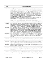
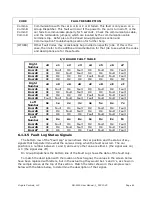
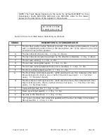
SIGNAL
DESCRIPTION for RED-INS FAULT
P
The car floor position when the fault occurred. The number will be between 1 and 9,
with 1 indicating the bottom floor, 2 the second floor, etc. 9 = no floor position.
A
The Emergency Stop Switch Input was On. 1 = Yes, 0 = No.
B
Input “INS” was On. 1 = Yes, 0 = No.
C
Input
“IN6” was On. 1 = Yes, 0 = No. This should be “0”
D
Input “IN9” was On. 1 = Yes, 0 = No. This should be “0”
E
Input “4A” was On. 1 = Yes, 0 = No. This should be “0”
F
Input “5A” was On. 1 = Yes, 0 = No. This should be “0”
G
Input “5G” was On. 1 = Yes, 0 = No. This should be “0”
H
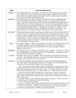
The Door Open Limit Input was On. (With selective doors, this indicates both Door
Open Limits were On, that is, neither door was full open). 1 = Yes (door not fully
open), 0 = No (fully open).
On SAPB/SBC this indicates Input “5H” was On. 1 = Yes, 0 = No.
S
hould be “0”
I
Up Level Input was On. 1 = Yes, 0 = No.
On SAPB/SBC only,
Input “INC” was On. 1 = Yes, 0 = No. This should be “0”
J
Down Level Input was On. 1 = Yes, 0 = No.
K
Car was in the Door Zone. 1 = Yes, 0 = No.
L
“LV” Input (monitors the contacts in parallel with the Door Contacts, in the Safety
String) was On. 1 = Yes, 0 = No.
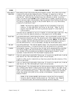
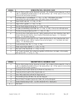
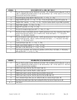
SIGNAL
DESCRIPTION for RED4INS FAULT
P
The car floor position when the fault occurred. The number will be between 1 and 9,
with 1 indicating the bottom floor, 2 the second floor, etc. 9 = no floor position.
A
The Emergency Stop Switch Input (terminal 4) was Off. (Inputs 4A, 5A, 5G, IN6,
IN9 should all be off.)
B
Input “INS” Inspection was On. (Inputs 4A, 5A, 5G, IN6, IN9 should all be off.)
C
Input “4A” was On.
D
Input “5A” was On.
E
Input “5G” was On.
F
Input “IN6” was On.
G
Input “IN9” was On.
H
Input “IN8” was On. (SAPB only)
I
Input “5H” was On. This may be Inputs “6A” and/or “6B”
for freight doors.
J - L
Not Used


