Virginia Controls, LLC
MH-3000 User Manual, 1_03C10-VC
Page 23
WARNING: The controllers have circuits that are fed from multiple
power supplies. Dangerous voltage levels may still be present even if
the disconnect for a particular car is turned off.
4.11.2
Homing
The Dispatcher will home cars to empty zones, giving priority to the Main Landing.
Automatic homing can be overridden by forcing one or more cars to home to a specific floor.
This can be done by enabling the Homing feature on the desired car(s). It is recommended
that automatic homing be used unless there are special requirements that necessitate
changing the homing operation.
A car will not home if it not in automatic (group) operation, if there are car calls
registered, or if the doors are open.
4.11.3
Communication
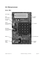
Confirm that the termination jumpers have been installed to connect the termination
resistors. These are two small jumpers just below the Group Communication Connector
block in the upper left corner of the CPU. (Refer to the diagram of the CPU)
Connect the communication cable (twisted pair in shield) from the Group Communication
Connector block of one car to the next car, forming a daisy chain that connects all the
controllers together. The cars should NOT be connected in a “star” format. Refer to the
schematic for a diagram of the correct connections. The order of the cars in the daisy chain
is not important. The drain wire
(or shield if no drain wire) should be connected to the “G”
(ground) terminal of the Group Communication Connector block at
one end only
. See the
diagram on the schematic.
When a car and Dispatcher are in operation, the LED D4 on the car should flash
repeatedly. (If LED D4 is ON, then there is a problem with one of the Input/Output boards.)
This indicates the car controller is communicating with the Dispatcher. The LED D4 on the
Dispatcher will flash if all cars are communicating properly. The status screen on the
Dispatcher will show which cars are communicating. The top left of the screen will read
“Comm=”. The letters following this message indicate the corresponding car is
communicating with the dispatch. For example, if the display shows
“Comm=A C “ then cars
A and C are communicating, but cars B and D are not.
If the Dispatcher is not communicating with one of the cars, check the communication
cables, the termination jumpers, and the grounding. If these look OK, but the CPUs are not
communicating, do a factory reset on the car(s) and Dispatcher. Look at the memory
locations in the table below to check the communications.
Address Description
Addresses on the Dispatcher
3186
Increases every time the Dispatch successfully communicates with car A
318E
Increases every time the Dispatch successfully communicates with car B
3196
Increases every time the Dispatch successfully communicates with car C
319E
Increases every time the Dispatch successfully communicates with car D
31BA
Increases every time the Dispatch fails to communicate with any car
Addresses on the Car Controllers
3190
Increases every time the car successfully communicates with the Dispatcher
3191
Increases every time the car fails to communicate with the Dispatcher


