background image


Virginia Controls, LLC 

MH-3000 User Manual, 1_03C10-VC 

Page 80  


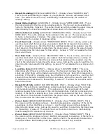
Dispatch Landing

 (DUPLEX and GROUP ONLY) - (Display shows "DISPATCH LDG")  

This is the dispatch landing for duplex or group systems.  One car will always home 
here.  This value can be set to any valid landing, as determined by the number of 
landings setting. 


Upper Home Landing

 (DUPLEX ONLY) - (Display shows "UPPER HOME LDG")  This is 

the home landing for the free car in a duplex system.  The free car can be selected to 
home to this landing, if desired.  This value should be set to be inside the upper zone, as 
determined by the Low Zone assignments shown later in the features settings. 


Alternate Home Landing

 (GROUP CAR CONTROLLERS  ONLY) - (Display shows "ALT. 

HOME LDG")  This is the alternate home landing for the car car.  The car can be forced 
to home to this landing, if desired.  This value can be set to any valid landing, as 
determined by the number of landings setting. 


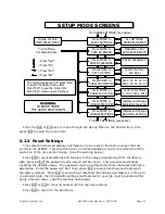
Front Door Code

 - (Display shows "FRONT DOOR CODE")  This is a binary coded value 

used to select which front openings are enabled.  Each bit corresponds to a landing.  If 
the bit for a landing is on, then the front doors at that landing will be enabled.  Use the 
chart shown in the schematic to determine the proper value.  Add up the value for each 

floor to determine the total value for this setting.  A value of “255”

 will enable the front 

doors at all floors. 


Rear Door Code

 - (Display shows "REAR DOOR CODE ")  This is a binary coded value 

used to select which rear openings are enabled.  Each bit corresponds to a landing.  If 
the bit for a landing is on, then the rear doors at that landing will be enabled.  Use the 
chart in the schematic to determine the proper value.  Add up the value for each floor to 

determine the total value for this setting.  A value of “0” will disable the rear doors at all 

floors. 


Low Zone Code

 (DUPLEX ONLY) 


(Display shows “LOW ZONE CODE”)  This value 

determines which floors are in the Low Zone.  The floors will normally be served by the 
Lobby car, other floors will normally be served by the Free car.  Each bit corresponds to 
a landing.  If the bit for a landing is on, then that floor is in the Low Zone.  Use the chart 
shown in the schematic to determine the proper value.  Add up the value for each floor 

to determine the total value for this setting.  A value of “3” will set the Low 

Zone as the 

bottom two floors. 


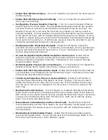
Dispatch Fail Calls

 (GROUP CAR CONTROLLERS  ONLY) - (Display shows "DISP. FAIL 

CALLS")  This sets the car calls that are entered automatically whenever the car loses 
communication with the Dispatcher.  If no calls are set, the car will park at the last 
landing served with its doors open if the communication fails.  Each bit corresponds to a 
landing.  If the bit for a landing is on, then a call will be entered at that floor.  Use the 
chart shown in the schematic to determine the proper value.  Add up the value for each 
floor to determine the total value for this setting. 


Zone 1 Code

 (GROUP DISPATCHER ONLY) - (Display shows "ZONE 1 CODE")  This is 

the code to set the landings in Zone 1.  Each bit corresponds to a landing.  If the bit for 
a landing is on, then that floor is in Zone 1.  Use the chart shown in the schematic to 
determine the proper value.  Add up the value for each floor to determine the total value 

for this setting.  A value of “3” will set Zone 1 as the bottom two f

loors.  Each landing 

must be assigned to one and only one zone. 


Zone 2 Code

 (GROUP DISPATCHER ONLY) - (Display shows "ZONE 2 CODE")  This is 

the code to set the landings in Zone 2. Each bit corresponds to a landing.  If the bit for a 
landing is on, then that floor is this Zone.  Use the chart in the schematic to determine 
the proper value.  Each landing must be assigned to one and only one zone. 

Содержание MH-3000

Страница 1: ...ion 1 03 C10b 02 12 2020 Member of CECA since 1998 Virginia Controls LLC 2513 Mechanicsville Turnpike Richmond Virginia 23223 Tel 804 225 5530 Fax 804 225 0116 email eng vacontrols com web site www vacontrols com MH 3000 USER MANUAL ...

Страница 2: ...Virginia Controls LLC MH 3000 User Manual ...

Страница 3: ...ng Switches 10 2 2 4 Terminal Landing Normal Slowdown Switches 10 2 2 5 Terminal Landing Normal Limit Switches 10 2 2 6 Terminal Landing Final Limit Switches 11 2 2 7 Emergency Terminal Landing Limit Switch 11 2 2 8 Hoistway Access Zone Switches 11 2 2 9 Door Open and Close Limit Switches 11 2 3 Machine Room Wiring 12 2 3 1 Incoming Power 12 2 3 2 Grounding 12 2 3 3 Pump Motor Wiring 13 2 3 4 Wye ...

Страница 4: ...unning Timers 19 4 9 Field Adjustable Features 20 4 10 Zoned Duplex Operation 20 4 10 1 Common Circuits 20 4 10 2 Next Car 20 4 10 3 Car Start 21 4 10 4 Homing 21 4 10 5 Communication 22 4 11 Zoned Group Operation 22 4 11 1 Common Circuits 22 4 11 2 Homing 23 4 11 3 Communication 23 4 11 4 Car Controller Settings 24 4 11 4 1 Dispatch Failure Calls 24 4 11 4 2 Car Homing 24 4 11 5 Dispatch Controll...

Страница 5: ...ton 36 5 5 1 4 CPU Connectors 37 5 5 1 5 S2 Slide Switch 39 5 5 2 Input Output Boards 40 5 5 2 1 Addressing 42 5 5 2 2 Terminal Wiring 42 5 5 2 3 Input Output LEDs 43 5 5 2 4 Board Status LED 43 5 5 2 5 I O Bus Communication Connectors 44 5 5 2 6 Programming Connector 44 5 5 2 7 Power Connector 44 5 5 2 8 Jumper Blocks 45 5 6 Motor Control 46 5 6 1 Across the line Starting 46 5 6 2 Wye Delta Start...

Страница 6: ...1 5 1 Messages Displayed on the Car Status Screen 71 6 1 5 2 Messages Displayed on the Dispatcher Status Screen 74 6 1 6 Go To Set Up Mode 74 6 1 7 Effect of Diagnostic Modes on Scan Time 75 6 2 Set Up Mode 76 6 2 1 How to Enter Set Up Mode 76 6 2 2 How to Exit Set Up Mode 76 6 2 3 Set Up Mode Screens 76 6 2 4 Reset Settings 77 6 2 5 Change Settings 78 6 2 5 1 Description of Settings 79 6 2 5 2 Nu...

Страница 7: ...istance 105 9 4 Changes for Program Revisions 105 9 4 1 Program Revision 2D 105 9 4 2 Program Revision 3A 106 9 4 3 Program Revision 3B 106 9 4 4 Program Revision 3C 106 10 CONTROLLER MAINTENANCE 108 10 1 Periodic Maintenance 108 10 2 Parts Replacement 108 10 2 1 CPU Exchange 108 10 2 2 EPROM Memory Chip Exchange 109 10 2 3 Input Output Board Exchange 109 11 FREQUENTLY ASKED QUESTIONS 111 11 1 Que...

Страница 8: ... you need to change the EPROM program chip on the CPU board make sure you read the instructions and know exactly how to install the new chip Plugging the EPROM chip in upside down may damage the chip Static electricity can damage the EPROM so avoid touching the pins on the chip and ground yourself by touching the controller cabinet before touching the chip or the controller Do not expose the EPROM...

Страница 9: ... circuit protection for the controller and motor Incorrect motor branch circuit protection may create a hazardous condition WARNING Proper grounding is vital for the safe operation of your system Bring the ground wire to the ground stud that is labeled GND or G You must choose the proper conductor size See national electrical code article 250 95 or the related local applicable code Pay special att...

Страница 10: ...between 0 C to 50 C 32 F to 122 F and 95 non condensing relative humidity Extended high temperatures will shorten the life of electronic components Provide adequate ventilation or air conditioning as required if necessary Avoid condensation on the equipment Keep the controller away from sources of condensation and water such as open windows as these can create a hazardous condition and can damage ...

Страница 11: ...the floor optional OR 4 the car is between the up and down slowdown points of that landing optional Conditions 1 and 2 are required to change the floor relays and initiate slowdown Condition 3 is required at the terminal landings but is optional at the intermediate landings Condition 4 is optional There are many acceptable methods of providing the floor switch signals such as by having a single Fl...

Страница 12: ... Down Level Switch to be equal to the length of the leveling vane target plus the desired Dead Zone distance usually 1 4 to 1 2 The actual length of the leveling target is not critical except in some short floor situations and is usually 6 10 Position the leveling vane target so that when the car is floor level the Up and Down Leveling Switches are centered around the vane target and both switches...

Страница 13: ...oor while on Hoistway Access at the bottom floor 2 2 9 Door Open and Close Limit Switches The Door Open Limit Switch is open when the doors are fully open and closed at all other times It will de energize the door open relays in the door operator when the doors have opened fully The Door Close limit Switch is open when the doors are fully closed and closed at all other times It will de energize th...

Страница 14: ...he appropriate size wires for the installation Consider the motor size and type of starter and also the length of wire required from the main power distribution center in determining the proper wire size Proper branch circuit protection and disconnect device s must be provided as required by applicable local state and national codes 2 3 2 Grounding WARNING PROPER GROUNDING IS VITAL FOR THE SAFE OP...

Страница 15: ...m of the overload and to terminals T4 T5 T6 See the schematic for specific connection details 2 3 4 Wye Delta Run Contact Wiring If a Wye Delta starter is used an auxiliary contact of the RU contactor may be connected in series with the up valves to prevent the car from starting to run up until the motor is in the Delta mode If this is not desired then jump the contact This will allow the valves t...

Страница 16: ...ter will read a short through the windings of the main control circuit transformer and or any power supplies With the fuses still removed apply power to the controller and verify that the voltage at the secondary of the main control circuit transformer CCXF is 110 125VAC 3 1 2 Input Output Wiring NOTE The input output boards are equipped with quick disconnect terminal blocks During the initial ins...

Страница 17: ...to be taken off Inspection Operation 3 2 1 Motor Rotation Check that the motor is rotating in the proper direction by turning on the power then briefly pushing in the motor starter PM on across the line installations STR on Wye Delta installations Observe the direction of rotation of the motor and if it is incorrect reverse any two of the main power leads at the main line disconnect If a Reverse P...

Страница 18: ...etup Menu where the first item is Reset factory Settings The password 911 should be entered when requested Press Esc to return the elevator to service As the wiring is completed the following modes of operation can be checked and used 4 1 Inspection Operation To run the car on Inspection Operation the safety string including the door contacts terminal landing normal slowdowns normals and finals sh...

Страница 19: ...her terminal landing when a slowdown switch and a leveling switch are energized at the same time NOTE If floor switches are used they should be maintained at the terminal landings so that they are energized whenever the car is in the slowdown zone at that landing Make your final adjustments for the slowdown targets All slowdown distances should be equal If a pulsing selector arrangement is used re...

Страница 20: ... at an intermediate landing and no other calls are in the system the doors will close after answering one of the calls then re open in response to the other call 4 6 Door Operation Verify that any required changes to the door operator as shown on the door operator drawings have been made correctly Check the Door Open and Close Limits for proper operation If the doors attempt to open for too long t...

Страница 21: ...remains on for an adjustable time and other calls are registered the stuck button call will be ignored and the car will answer the other call s The car will return to the stuck button call as it answers other calls and the stuck button timer sequence will be repeated 4 8 2 Running Timers If the car runs up for an adjustable time without changing floors then low oil shutdown operation will be initi...

Страница 22: ... value is normally the Lobby Main landing and any landings below the Lobby Main landing All other landings are in the Upper Zone If a car is Next in a zone then it will answer calls in that zone otherwise it will answer calls in the other zone If both cars are in service a car will always be homed to the Main Lobby level 4 10 1 Common Circuits Several circuits need to be energized when either car ...

Страница 23: ... normal group operation 5 The other car is not in normal group operation 6 The other car has a call behind it 7 Emergency Power is activated and this car is assigned to run 4 10 4 Homing If there are no cars at the Main Dispatch landing the Next car in the Low Zone will home or return to the Main Dispatch Landing If there is no Next Car in the Low Zone then the first available car will home to the...

Страница 24: ...ontroller for each car and one MH3000 controller as a Dispatcher The Dispatcher receives all hall calls and allocates them to the cars The car controllers provide status information back to the Dispatcher to allow the optimum allocation of hall calls The Dispatcher will home the cars giving priority to the Main Landing and putting the other cars in empty zones as the cars become available The numb...

Страница 25: ...terminal of the Group Communication Connector block at one end only See the diagram on the schematic When a car and Dispatcher are in operation the LED D4 on the car should flash repeatedly If LED D4 is ON then there is a problem with one of the Input Output boards This indicates the car controller is communicating with the Dispatcher The LED D4 on the Dispatcher will flash if all cars are communi...

Страница 26: ...r can be forced to home to either the Dispatch Landing or the Alternate Home Landing This will override the automatic homing from the Dispatcher It is recommended that the Dispatch be allowed to home the cars and that forced homing be left off 4 11 5 Dispatch Controller Settings Settings in the Dispatcher are changed in the same way as on the car controllers as described in this manual in the sect...

Страница 27: ...le time setting Hold Up Heavy after Hall Call after the Main Landing Up Hall Call has been answered So if no cars leave the Main Landing loaded and the Main Landing Up Hall Call is not registered the Up Heavy program will time out Inputs are normally provided to initiate these programs manually These can be connected to a time clock if desired to initiate the program at certain times of the day Th...

Страница 28: ...ler is initially installed The Power Supply section includes the required transformers and fuses to power the Microprocessor system and the Relay Interface The Relay Interface includes the required relays and contactors to interface the field signals and devices to the microprocessor This usually includes a printed circuit board for normal signals as well as other relays or contactors for signals ...

Страница 29: ...Virginia Controls LLC MH 3000 User Manual 1_03C10 VC Page 27 5 2 Fuses The fuse type and rating is shown on the schematic NOTE Only replace fuses with fuses of the same type and rating ...

Страница 30: ...wer Supply then measure the output again If the output is now 12VDC check the load to make sure it is not shorted NOTE Output voltages below 12VDC may cause erratic operation 5 4 Safety Interface Board The Safety Relay Interface may be provided as a printed circuit board or as discrete surface mounted relays or a combination of both The Safety Relay Interface provides interface signals to the Moto...

Страница 31: ...Virginia Controls LLC MH 3000 User Manual 1_03C10 VC Page 29 5 4 1 MH4 5 4 2 MH5 ...

Страница 32: ... voltage over voltage and voltage unbalance must be sensed for a continuous trip delay period before the output is de energized The output will not de energize if the fault is corrected during the trip delay The LED flashes red during the trip delay then glows red when the output is de energized The restart delay begins as soon as the output relay de energizes If the restart delay is completed whe...

Страница 33: ...hes MH 4 Board version shown The Bypass Switches bypass either the Car Door Contact s or the Hall Door Contacts as required by the appropriate codes They may only be used on Inspection Operation The code requires using these switches to run the car on Top of Car Inspection with the doors open instead of putting jumpers around the Door Contacts Moving either of these switches to the Bypass position...

Страница 34: ...uttons are not active when on Car Top Inspection To operate the car slide the S3 Inspection Sw to INSP then press the RUN and UP or RUN and DOWN buttons together WARNING Use extreme caution when operating the car from the machine room Make sure it is safe to move the car 5 4 7 Connections The top terminal strip s of the Safety Interface Board is generally used for factory connections The bottom te...

Страница 35: ...anual 1_03C10 VC Page 33 5 5 Microprocessor 5 5 1 CPU LCD Display CPU Status Reset Button LEDs Termination Jumpers Group Communication Keypad Connector I O Board Communication Connector Battery S2 Slide Sws 12VDC Power EPROM Supply Socket ...

Страница 36: ...atus of key parameters and functions in the RAM memory The battery life is approximately 5 years WARNING Replace the battery with RENATA 3V Lithium battery Part No CR2032 Only Use of another battery may present a risk of Fire or Explosion CPU LCD DISPLAY DISPLAY D1 D2 D3 D4 D5 G D EPROM INPUT OUTPUT BUS CONNECTOR LEDs KEYPAD CONNECTOR KEYPAD DASHED MOUNTED OVER CPU COMMUNICATION CONNECTOR TERMINAT...

Страница 37: ...Service Low Oil Shutdown or any other mode that will cause the car to ignore Hall Calls D2 Fire Service This LED should be off during normal operation It will be lit if the car is on Fire Service Phase 1 Hall or Phase 2 Car D3 Shutdown This LED should be off during normal operation It will be lit if the Up Run timer indicated the car has been running up for a preset adjustable time without passing...

Страница 38: ...ication section D5 Watchdog This LED will flash regularly about once per second if the CPU is operating properly NOTE The LED will flash every 10 seconds if the car is not in the run mode If the LED stops flashing reset the CPU by cycling the Main Line Disconnect Switch or pressing the Reset Button on the CPU NOTE If the diagnostic mode is changed to monitor the Internal Memory or the Setup Mode i...

Страница 39: ... directly on the connector The LCD display can be removed for replacement If it is removed then set switch 1 on the Slide Switch S2 to the OFF position before turning the power back on This will ensure the CPU does not try to write to the LCD screen while it is removed It is recommended that the LCD display AND the Keypad be removed together since if the LCD display only is removed and the keypad ...

Страница 40: ...e correct terminals The upper terminal is and the lower terminal is The connector is shaped so that the mating terminal plug can not be inserted upside down 5 5 1 4 5 Input Output Bus Connector The Input Output Bus Connector is on the left of the CPU board An RJ45 style cable is used to connect to the first I O board The other I O boards are connected to each other using a daisy chain method with ...

Страница 41: ...activate the display and show the Car Status screen press any key This mode should be used if the LCD is to be removed for any reason It is recommended that if the LCD Display is removed that you also remove the keypad since pressing a key with the LCD removed could lock up the CPU as it attempts to write to the LCD Display 5 5 1 5 2 Switch 3 on S2 Slide Switch Switch 3 on the CPU Slide Switch S2 ...

Страница 42: ... shown below to identify the key components Removable Terminals Commons I O numbers Programming Port Input LEDs Output LEDs with number with number below LED below LED I O Comm Address Connector IN Switches Status LED 12VDC I O Incoming Communication Power Connector OUT Input LEDs Output LEDs with number with number above LED above LED ...

Страница 43: ...e removable terminal blocks at the top and bottom of the I O boards Fuses are provided externally not on the I O boards Programming Connector Output LEDs 9 16 Address Sw Block Commons Commons I O Communication Bus OUT Connector TYPICAL I O BOARD Terminals Output Relays 1 8 C1234C5678 C1234C5678 12345678 12345678 10 12 14 16 9 11 13 15 10 12 1416 9 11 13 15 C 10 12 13 15 9 11 C 14 16 15 C 10 12 13 ...

Страница 44: ...he SAME ADDRESS as the board it was replacing The address of each I O point is determined by the Board Number 1 through 8 then the Point Number 1 through 16 The board number is used in the Show I O screen to indicate which board is being monitored 5 5 2 2 Terminal Wiring Wiring to Inputs 1 8 is at the TOP LEFT of the I O board wiring to the Outputs 1 8 is at the TOP RIGHT of the I O board Wiring t...

Страница 45: ...arting from the left for the top group and 9 16 starting from the left for the bottom group The point numbers are silk screened on the board adjacent to the actual LEDs for each point The LEDs have a D number silk screened next to the LED This is a component identifier and does not correspond to their address The address number is the slightly larger number between the LED and its resistor Each LE...

Страница 46: ...OMM OUT on the CPU is cabled to the I O COMM IN of the first I O board The I O COMM OUT of that board connects to the I O COMM IN of the next board and so on The addresses of the boards must correspond to their position in the daisy chain 5 5 2 6 Programming Connector This connector is used to program the microprocessor on the I O board It is not used once the I O board is programmed 5 5 2 7 Power...

Страница 47: ...ame as putting a jumper from the output point to the same numbered input point For example a jumper placed on the pins labeled 3 would jump input point 3 to output point 3 WARNING When an input and output are jumped together always connect the field wiring to the OUTPUT terminal Do NOT connect the field wiring to the Input terminal as this could overload the wiring on the board Inputs and outputs ...

Страница 48: ... A wide variety of motor starting options are available Please consult the as built schematics to determine the exact starting configuration 5 6 1 Across the line Starting Connect Building Supply Power Here Contactor Electronic Overload Connect Motor Leads Here Auxiliary Contacts ...

Страница 49: ...nia Controls LLC MH 3000 User Manual 1_03C10 VC Page 47 5 6 2 Wye Delta Starting Connect Building Supply Power Here Run Contactor Start Contactor Mechanical Interlock Overload Relay Connect Motor Leads Here ...

Страница 50: ...Virginia Controls LLC MH 3000 User Manual 1_03C10 VC Page 48 5 6 3 Solid State Starting Connect Building Supply Power Here Connect Motor Leads Here Lead Motor Here Fault Contactor ...

Страница 51: ...the protected load a low battery shutdown may occur Advance warning of a low battery condition begins approximately two minutes before the final shutdown This alarm will be a continuous beeping sound and cannot be silenced Normally this condition should not occur if batteries were previously charged fully due to remote shutdown capability of BORIS and Virginia Controls controller Special features ...

Страница 52: ...he CPU If S2 switch 1 is ON then the Car Status screen will be displayed and if S2 switch 1 is OFF then the screen will be blank until a key is pressed It will then show the Car Status screen Press Esc to return to the Run Mode menu screens Pressing Nxt or Prv will scroll through the available screens in the Run Mode To select a display press Nxt or Prv to show the desired item then press Ent to s...

Страница 53: ... date on the bottom line and the base program code on the top line The controller displays the Car Status screen when the Banner screen is exited To Go to Setup Menu see below From Setup Mode To Setup Mode To Show Car Status see above VA CONTROLS BANNER SCREEN Press ENTER to SHOW CAR STATUS Press ENTER to SHOW INT MEMORY Press ENTER to SHOW I O STATUS 0400 00 00 00 00 0404 00 00 00 00 Virginia Con...

Страница 54: ...O Screen matches the I O boards then the checksum in the communication is incorrect This will cause the CPU to ignore the data and not pass it to the main program To determine which board is causing the communication failure refer to the section on troubleshooting suggestions for I O board faults 6 1 2 1 Moving Around in I O Status Screen Press Nxt or Prv to scroll through the I O Press Aux to tog...

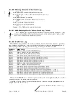
Страница 55: ... Number 01 is the fault number shown on the top left of the Fault Log screen It is a hexadecimal number from 00 to 3E decimal 62 with 00 being the most recent fault Press Nxt to scroll through the fault log showing the next older fault Press Prv to show the next most recent fault You can press 0 to jump to the most recent fault fault 00 6 1 3 3 Fault Time Stamp 09 40 is the time stamp for the faul...

Страница 56: ...Bit Features will be labeled Disable Non Shutdown Faults in the Fault Log Turn this feature on to disable non shutdown faults This may be useful if you are trying to track down a specific fault and you do not want the fault log to contain minor faults Refer to the section on Changing Features for instructions on settings the proper Bit Feature to disable non shutdown faults Disabling non shutdown ...

Страница 57: ...tive rollover faults will be combined into one rollover fault and the number on the lower right will indicate how many additional rollovers were combined indicating there were no faults for that many additional days 23 00 00 ROLLOVR 11 13 2 24 09 30 LOW OIL 3 0110 1001 0000 25 00 00 ROLLOVR 11 07 5 For example if faults 23 24 and 25 were as shown above this indicates a rollover code 25 was combine...

Страница 58: ...ed to close properly when they were parking or when the car was ready to run for the next call This fault will not be caused by keeping the doors open through the normal means Door Open Button Safety Edge Infra red Unit etc but only if the doors should be closing but were not able to close The probable causes are 1 Door Close Limit Switch failure 2 Door Contacts failure 3 door operator failure 4 d...

Страница 59: ...tion Note If Fire Service is not provided or it is desired to bypass Fire Service during initial installation then jump the Hall Fire Switch Bypass Position Input MRSMOKE The Machine Room or Shaftway Fire Sensors were initiated This signal is required by the 1998 ANSI code and will start the Fire Light flashing It must be reset by turning the Hall Fire Switch to Bypass SHUNT The Shunt Trip Input w...

Страница 60: ...Y FS Relay Fault The car attempted to run floor to floor 20 times but did not make a floor change This is normally caused by the FS relay failing to cut out the leveling switches so that the car cannot leave the floor When this fault is detected the fault will be logged and the car will shut down RED ESB or RED1ESB Redundancy Fault in the ESB Emergency Stop Sw Bypass circuit The input that monitor...

Страница 61: ...ancy fault are custom to help determine the cause of the fault Refer to the section that describes the Fault Log Status Signals for a description of the signals This fault can be disabled by turning on Switch 3 on the CPU Slide Switch S2 This also turns on the Fire Buzzer output as a reminder to turn off the defeat RED SAF or RED3SAF Redundancy Fault in the Safety Circuit The condition of the Door...

Страница 62: ...turning on the CPU DIP Switch 4 or by momentarily jumping the Fault Reset Input OIL SW Low Oil Switch Fault The Low Oil Switch closed The car will return to the lowest landing and shut down To reset the fault cycle the power to the controller FLOOD Flood Switch tripped This will shut the car down at the designated Flood landing The Flood Landing is the second landing by default but can be changed ...

Страница 63: ...ult OK Fault OK Fault Board2 OK OK Fault Fault OK OK Fault Fault Board3 OK OK OK OK Fault Fault Fault Fault Board4 Fault Fault Fault Fault Fault Fault Fault Fault Left Number 0x 1x 2x 3x 4x 5x 6x 7x Board5 OK Fault OK Fault OK Fault OK Fault Board6 OK OK Fault Fault OK OK Fault Fault Board7 OK OK OK OK Fault Fault Fault Fault Left Number 8x 9x Ax Bx Cx Dx Ex Fx Board5 OK Fault OK Fault OK Fault OK...

Страница 64: ...B The last direction selected as shown by the direction indicators 1 Up 0 Down C The car was running 1 Yes 0 No D The car was running fast speed 1 Yes 0 No E The car was running between floors not re leveling 1 Yes 0 No F The Door Contacts Input was On 1 Yes 0 No G The Door Close Limit Input was On With selective doors this indicates either Door Close Limit was On that is one or both of the doors ...

Страница 65: ...s door open 0 No door closed H The Door Open Limit Input was On With selective doors this indicates both Door Open Limits were On that is neither door was full open 1 Yes door not fully open 0 No fully open I Up Level Input was On 1 Yes 0 No J Down Level Input was On 1 Yes 0 No K Car was in the Door Zone 1 Yes 0 No L LV Input monitors the contacts in parallel with the Door Contacts in the Safety S...

Страница 66: ...pen Limit Input was On With selective doors this indicates both Door Open Limits were On that is neither door was full open 1 Yes door not fully open 0 No fully open I Up Level Input was On 1 Yes 0 No J Down Level Input was On 1 Yes 0 No K Car was in the Door Zone 1 Yes 0 No L LV Input monitors the contacts in parallel with the Door Contacts in the Safety String was On 1 Yes 0 No SIGNAL DESCRIPTIO...

Страница 67: ...open 0 No fully open On SAPB SBC this indicates Input 5H was On 1 Yes 0 No Should be 0 I Up Level Input was On 1 Yes 0 No On SAPB SBC only Input INC was On 1 Yes 0 No This should be 0 J Down Level Input was On 1 Yes 0 No K Car was in the Door Zone 1 Yes 0 No L LV Input monitors the contacts in parallel with the Door Contacts in the Safety String was On 1 Yes 0 No SIGNAL DESCRIPTION for RED4INS FAU...

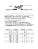
Страница 68: ...ion 0520 Month of start of current historical log 0521 Date of start of current historical log 0522 Number of Faults Characters 1 and 2 0523 Number of Faults Characters 3 and 4 0524 Number of Floor to Floor Runs Characters 1 and 2 0525 Number of Floor to Floor Runs Characters 3 and 4 0526 Number of Door Cycles Characters 1 and 2 0527 Number of Door Cycles Characters 3 and 4 0528 Month of start of ...

Страница 69: ...oor cycles is 1619 hex which is 4096 1536 16 9 5657 dec After the number of days set in address 0401 default is 60 the values from the current Historical Log addresses 0520 0527 are moved to the Previous Log addresses 0528 052F and the current log is cleared out The current date is loaded into the start addresses for the new current historical log Table to determine the Decimal Value of a 4 digit ...

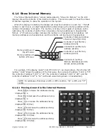
Страница 70: ...4 FF 00 2D 14 as shown above then the top left number 1024 shows the address of the first value the contents of address 1024 is FF the contents of address 1025 is 00 the contents of address 1026 is 2D and the contents of address 1027 is 14 with each value being shown in hexadecimal NOTE For addresses that show an ON or OFF condition 00 is OFF and FF is ON 6 1 4 1 Moving Around in the Internal Memo...

Страница 71: ...nge operation in the Show Internal Memory Mode They now show the status of the top 4 words being displayed Specifically D1 shows the status of the 1st bit of the top left word being displayed D2 shows the status of the 2nd bit of the 2nd left word being displayed D3 shows the status of the 3rd bit of the 3rd top left word being displayed and D4 shows the status of the 4th bit of the 4th top left w...

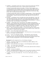
Страница 72: ...resses being displayed by 1 Press 3 to increase the addresses being displayed by 4 Press 6 to decrease the addresses being displayed by 4 Press 2 to increase the addresses being displayed by 10 Hex Press 5 to decrease the addresses being displayed by 10 Hex Press 1 to increase the addresses being displayed by 40 Hex Press 4 to decrease the addresses being displayed by 40 Hex Press 8 to enter a val...

Страница 73: ...he car is not on one of the special operations shown above Message 2 will be replaced with one of the following messages 1 SHUNT the Shunt Trip input is enabled The car will stop at the next landing open its doors and shutdown 2 SMOKE the Machine Room Shaftway Fire detectors Input is energized 3 FIRE2 the car is on Fire Service Phase 2 car 4 FIRE1 the car is on Fire Service Phase 1 hall 5 FLOOD th...

Страница 74: ...ts that bypass the Door Contacts on Inspection or Access operation was closed when the car was not on Inspection or Access or terminal 4 was not hot Check the Door Contact circuit for jumpers or shorts Cycle the power to reset the fault 12 DZFlt a Door Zone Fault was detected The Door Zone input was on while the car was running fast speed OR the Door Zone input came on before an Up or Down Level S...

Страница 75: ...5 SS the car is running slow speed 6 no message the car is not running and it is not in the door zone If the appropriate fault exists Message 7 and 8 will be replaced with one of the following messages 1 IO FAULT the communication with one or more of the I O boards has failed 2 DrChkFLT the Door Closed Input is on and the Door Closed Limit is on indicating the Door Contacts have been jumped 3 DrLm...

Страница 76: ... B1 C1 D1 Message 1 shows which car or cars are communicating with the Dispatcher If a car is communicating the letter for that car will be visible For example Comm A C indicates the Dispatcher is communicating with cars A and C only Message 2 will be replaced with one of the following messages 1 IO Flt the communication with one or more of the I O boards has failed 2 FIRE the system is on Fire Se...

Страница 77: ...n taking about 7 milliseconds Servicing the LCD display is one of the more time consuming tasks that the microprocessor does so when the LCD display needs to be updated regularly the microprocessor must slow down to allow it to accept the data Consequently the scan time is slower when in the Show I O Status and Show Internal Memory Modes than when displaying other screens The car will still operat...

Страница 78: ...very 10 seconds to indicate the CPU is not locked up 6 2 2 How to Exit Set Up Mode Press Esc from the Set up Menu to return to the Run Mode The controller will start running again and will be in the Show Car Status Mode LED D5 will start flashing about once a second indicating the CPU is scanning LEDs D1 D4 will revert to their normal operation Note It may be necessary to press Esc to exit a sub m...

Страница 79: ...b is a standard job then the specific settings and features for your job must be entered after doing a factory reset See the warning note below Press Nxt or Prv to move to another item in the Set up Menu Press Esc to return to the Run Mode To RESET SETTINGS see above To CHANGE SETTINGS see below Virginia Controls MAIN SETUP MENU Press ENTER to RESET SETTINGS Press ENTER to CHANGE SETTINGS Press EN...

Страница 80: ...ection or remove the field wire from terminal 23 3 Jump terminals 1 to 21 and 22 Up and Down Level Switch Inputs 4 Turn the power back on for 10 seconds Inputs 1 and 2 on Board 1 should both be ON and Input 3 on Board 1 should be OFF 5 Turn off the power 6 Remove all jumpers and put the car back on normal operation 6 2 5 Change Settings Use this selection to change the settings described below Eac...

Страница 81: ...tion number for this car It is used in the communication to the Dispatcher and is a number between 1 and 4 The number assigned to each car in the group MUST be different The car assigned id 1 will show up on the Dispatcher as car A id 2 is car B id 3 is car C id 4 is car D You should not normally change this value as it has been assigned in the factory If you do change it make sure that two cars d...

Страница 82: ...s setting A value of 0 will disable the rear doors at all floors Low Zone Code DUPLEX ONLY Display shows LOW ZONE CODE This value determines which floors are in the Low Zone The floors will normally be served by the Lobby car other floors will normally be served by the Free car Each bit corresponds to a landing If the bit for a landing is on then that floor is in the Low Zone Use the chart shown i...

Страница 83: ...lay shows CAR CALLS UPHVY This is the number of Car Calls that must be entered as a car leaves the lower landings to initiate the Up Heavy Traffic Program This will affect the assignment of calls and the homing scheme See the section on Zoned Group Operation for a more complete description of the traffic programs 6 2 5 3 Bit Features The Bit Features are multiple features combined into several set...

Страница 84: ...is value This timer is only used with the Jack Resynchronization feature Custom Time 0 1 Display shows CUSTOM TIME 0 1 This is a reserved value that is not assigned but may be assigned a function for a specific job The time base for this timer is not preset and may change depending on its use Refer to the Settings sheet in the schematic to see if and how this setting is used Custom Time 0 2 Displa...

Страница 85: ...BACK CALL DELAY This is the time in tenths of a second that the back call signal will be delayed before letting the other car respond to calls behind this car The normal setting is 10 for a time of 1 second Up Main Landing Hall Call Delay GROUP DISPATCHER ONLY in tenths of a second Display shows UP MAIN LDG DLAY This is the time in tenths of a second that the Up Main Landing Hall Call must be regi...

Страница 86: ...he car are disabled so that the car can answer other registered calls This operates as a stuck button timer The normal setting is 15 seconds Door Stuck Time in seconds Display shows DOOR STUCK TIME This is the time delay before stopping a door open or close cycle The normal setting is 20 seconds Door Stuck Reset Time in seconds Display shows DOOR RESET TIME This is the time that the doors are held...

Страница 87: ...lapsed Switch Input fails or is not provided This value is only used with the Jack Resynchronization feature Custom Time 2 1 in seconds Display shows CUSTOM TIME 2 1 This is a reserved value that is not assigned but may be assigned a function for a specific job Custom Time 2 2 in seconds Display shows CUSTOM TIME 2 2 See Custom Time 2 1 Custom Time 2 3 in seconds Display shows CUSTOM TIME 2 3 See ...

Страница 88: ... Fire Code features Enable New York Fire Code Turn this feature on to enable New York Fire Code Enable 2001 Chicago Fire Code Turn this feature on to enable 2001 Chicago Fire Code Enable 1998 Chicago Fire Code Turn this feature on to enable 1998 Chicago Fire Code This feature is not provided on programs after 11 2007 Use 2 Inputs for 1998 Chicago Fire Code Turn this feature on to use 2 inputs for ...

Страница 89: ...lls but also requires that the EMT Car Sw be left ON until the car reaches its destination Enable Pulsing Selector off Floor Sws Turn this feature on to enable a pulsing floor selector rather than individual Floor Switches With a pulsing arrangement there is an up or a down pulse to change floors Additionally at the terminal landings enabling the up pulse input and the door zone input will reset t...

Страница 90: ...Independent only Turn this feature on to change the operation of the Medical Emergency Buzzer output With the feature disabled factory default the buzzer will come on while the car is returning to the Medical Emergency floor in response to the hall Medical Emergency Switch If the feature is enabled the buzzer will come on if the car is on Independent Service and a hall Medical Emergency Switch is ...

Страница 91: ... Fire Service Overrides Flood Operation Turn this feature on to allow Fire Service to override Flood Service The car will return to the Main Fire Floor even if that is the bottom landing Flood Operation Overrides Hall Fire Service Turn this feature on to allow Flood Service to override Fire Service and cause the car to leave the bottom landing even if that is the designated Fire landing If this fe...

Страница 92: ...s the Nudging Buzzer output is the only output specifically required The output for this feature must have been assigned for this feature to work properly Enable CKO Output Turn on to enable the CKO Car Call Cutout Override output The output for this feature must have been assigned for this feature to work properly Enable PI Blanking Fire Output Turn on to use the Fire Light output as a Position I...

Страница 93: ...spection to Normal This feature is only used with the Jack Resynchronization feature Disable Negative Pressure Sw on Jack Resync Turn this feature on to disable the Negative Pressure Switch feature when the car is doing a Jack Re Sync Enable Jack Out Of Synchronization Input Enable this bit feature to allow Jack Re synchronization to be initiated by the Jack Out Of Sync Input This feature is only ...

Страница 94: ...erve this opening but this car does Only this car serves Rear Calls at Ldg 1 Turn this feature on if the other car in the duplex does not serve this opening but this car does Only this car serves Rear Calls at Ldg 2 Turn this feature on if the other car in the duplex does not serve this opening but this car does Only this car serves Rear Calls at Ldg 3 Turn this feature on if the other car in the ...

Страница 95: ...not opened This feature should only be enabled if there are power operated doors that also have a Door Open Limit signal connected to the controller Enable Timed Door Open Fault in Fault Log Turn this feature on to enable the TDOPEN fault in the Fault Log This feature should only be enabled with power operated doors If it is enabled with manual doors then a fault will be logged every time the car ...

Страница 96: ...n to allow a car in Zone 1 to answer a hall call in Zone 2 if there is no car in Zone 2 If this feature is off then a car from Zone 3 will be given the call Enable Car A Turn this feature on to enable Car A Enable Car B Turn this feature on to enable Car B Enable Car C Turn this feature on to enable Car C Enable Car D Turn this feature on to enable Car D 6 2 6 Change Features Use this selection to...

Страница 97: ...if the Electric Eye input is energized This means the door will only close at slow speed if the Electric Eye is blocked NOTE Door Nudging operation requires an optional Nudging Buzzer output and Reduced Speed Door Closing output One Stroke Down Lanterns Display shows 1 STROKE DN LANT The lanterns are normally provided with two strokes for the down direction Enable this feature to provide only one ...

Страница 98: ...HOME ALL TO MAIN Enable this feature to home all cars to the Dispatch Landing Some installations require specific settings or features that are not included in the standard program In this case a separate sheet or sheets will be provided that describe the operation of these settings or features and what the factory default settings are Normally special features are included in the Bit Features set...

Страница 99: ...nd minute 0 59 ENTER YEAR 00 99 01 In each case press Ent to accept the current value or enter the correct value then press Ent If an incorrect value is entered just enter the correct value again and press Ent If you press Esc during this sequence then the time and date will not be updated and the display will return to the setup menu After all the data has been entered the screen will display the...

Страница 100: ... entered by pressing the 7 key when the display is activated from the blank screen after a power cycle or when the VA CONTROLS banner is displayed after pressings Esc from the Run Mode menus This allows the password to be entered without stopping the controller The password can be given to all authorized personnel that is those who would need to change settings or features on the controller WARNIN...

Страница 101: ...e same board Input Point 1 will turn on Output Point 1 Input Point 2 will turn on Output Point 2 etc This allows the inputs and outputs to be tested by jumping the desired input on and verifying that the proper output comes on Note The outputs are updated once every tenth of a second so there may be a slight delay in turning on the output after the input has been energized WARNING Be very careful ...

Страница 102: ...Circuit board A1 IAS1 2 INSPECTION ACCESS RELAYS on Printed Circuit board A1 INS INSPECTION RELAY on Printed Circuit board A1 O DOOR OPEN RELAY in MODSS on top of the car if used A5 PM STARTER ACROSS THE LINE START B4 B7 PMP PUMP MOTOR PILOT RELAY 110VDC on Printed Circuit board A2 RU MOTOR RUN CONTACTOR WYE DELTA START B1 B6 SP1 5 SPARE RELAYS Function varies per job on Printed Circuit board A1 S...

Страница 103: ...FOR 3 POLE OVERLOAD NEMA SQD Types B CC DD B5 Y D REVERSING CONTACTOR IEC SQD Telemechanique LC2 ____G6 B6 ACROSS THE LINE STARTER IEC SQD Telemechanique LC1 ____G6 B7 3 POLE OVERLOAD IEC SQD Telemechanique LR____ TRANSFORMERS FUSES TERMINALS C1 460 230 208 230 115 600VA 300VA SQD 9070K____D48 C2 250V INSTANTANEOUS FUSE BUSSMAN TYPE BAF C3 250V FUSEHOLDER CURTIS PW1F C4 TRACK FOR 250V FUSEHOLDERS ...

Страница 104: ...R TAYLOR 99010 E6 1 W DUCT MOUNTING CLIPS TAYLOR 08010 E7 CONTROLLER ENCLOSURE V C SIZE E8 STARTER ENCLOSURE V C SIZE All parts are commercially available from the manufacturer or from Virginia Controls Inc ask for the Parts Department or send an email to parts vacontrols com Parts are subject to change without notice Consult Virginia Controls LLC for current pricing information Non standard mater...

Страница 105: ...ld be in the wiring to the position indicator or perhaps the position indicator light has burned out Similarly with input points check that the input module light is on that there is power at the terminal and if not then the problem is external If it is determined that the problem is with the microprocessor then the next step is to determine if the problem is in the hardware or the software Using ...

Страница 106: ...oards for the right code number and the bottom section shows the codes for the left code number Right Number x0 x1 x2 x3 x4 x5 x6 x7 x8 x9 xA xB xC xD xE xF Board1 OK Fault OK Fault OK Fault OK Fault OK Fault OK Fault OK Fault OK Fault Board2 OK OK Fault Fault OK OK Fault Fault OK OK Fault Fault OK OK Fault Fault Board3 OK OK OK OK Fault Fault Fault Fault OK OK OK OK Fault Fault Fault Fault Board4...

Страница 107: ...I O Board Replacement WARNING When replacing a board the Address Switch setting on the new board must be set to match the old board To replace an I O board TURN THE POWER OFF Unplug all the terminal blocks at the top and bottom of the board Unplug the Power Connector and the I O Bus Connectors Remove the screws holding the board in place Install the new module by reversing the above steps 9 3 Fact...

Страница 108: ... Settings sheet 9 4 3 Program Revision 3B Approximate Date of implementation 05 1 2005 Redundancy Faults were given specific Fault Codes and Status Screen Messages The Fault Status Codes in the Fault Log were customized for Redundancy Faults The Rollover Fault code was modified so that consecutive Rollovers would be combined into one fault with the number of fault free days shown on the lower righ...

Страница 109: ...e Date of implementation 1 01 2009 Negative Pressure Switch was added as an input allowing greater control of the operation if it tripped Minor Revision 3C09 Approximate Date of implementation 3 01 2010 9C 6 2010 Minor changes to Door Hold Open operation 9D 9 2010 Minor changes to Medical Emergency and Fire Service operation 9E 3 2011 added flashing Fire Light per latest code 9F 11 2011 minor chan...

Страница 110: ...hen checking to make sure the onboard clock is still correct To check the time press Nxt until the display shows Press ENTER to SHOW FAULT LOG Then press Ent then press to show the current time If the date had been set and it now shows the date as 01 01 00 then the battery is dead Change the battery and set the time Keep the controller clean and dry Power supplies and processor chips in particular...

Страница 111: ... a small screwdriver or other appropriate tool pry out the old EPROM chip by inserting the screwdriver between the chip and its socket from the right side Gradually work the chip out trying to avoid swinging it out which would bend the pins at one end but rather prying it straight out by working the screwdriver under the chip 3 Insert the new EPROM chip by orienting it properly so that the notch i...

Страница 112: ...inal blocks since the wiring will normally hold them in the proper place so that it is obvious which block goes where If there is any doubt about their location then mark the terminal blocks to show where they should be re installed 4 Unplug the I O Bus Connectors and power connector 5 Remove the screws holding the I O board in place 6 Install the new I O board by reversing the previous steps ...

Страница 113: ...h If it happens regularly at a particular floor there is probably an overlap between Floor Switches In this case either separate the Floor Switches or targets so there is no overlap or turn on the Short Floor feature described above in the features section Q The doors do not operate properly on Fire Service Check the Door Open and Door Close Limit Switches for proper operation Most problems with F...

Страница 114: ... values must be changed but the other values should be checked Q How do I check the current values of the settings and features 1 Go to the Setup Menu 2 Select the menu item Change Settings and press Ent then enter the password 911 3 Scroll through the settings by pressing Nxt The settings will not be changed unless a new value is entered and then Ent is pressed 4 Press Esc then Nxt to go to the C...

Страница 115: ...s is custom designed for each installation Though there are some strong similarities between similar jobs it is strongly recommended that you have accurate prints schematics before working on any of our control systems We require the job number for any installation before we can offer practical help with any problems on that installation so that we can refer to the actual prints for that job It is...

Страница 116: ...plex 20 22 36 37 57 96 E EPROM 6 26 35 77 109 F Factory Reset 16 Failure Timers 19 Fault Code 54 Fault Log 52 53 54 61 66 76 96 Features 20 76 81 82 84 94 95 111 112 Fire Service 11 19 20 21 35 57 71 72 84 87 95 98 111 Flood 60 71 89 106 G Grounding 7 9 12 14 H Hexadecimal Conversion Table 68 Historical Log 66 Homing 21 23 84 96 Humidity 8 I I O Fault 60 I O Status 52 Independent 17 21 35 71 72 84...

Страница 117: ... 79 96 97 98 112 Running Timers 19 S S2 Slide Sw 37 39 50 112 Selector 10 96 Settings 20 76 77 78 79 82 86 95 111 112 Set Up Mode 75 76 Starters 46 Start Up 14 Status 36 39 43 50 51 52 61 70 71 74 75 76 103 104 Stuck Button 19 Switches 10 11 43 52 57 60 71 96 109 111 Floor 9 Leveling 10 19 57 71 83 Limit 10 11 18 56 57 62 63 64 65 73 111 Slowdown 10 11 17 Zone 10 11 19 20 56 58 62 63 64 65 72 73 8...

Отзывы: