Virginia Controls, LLC
MH-3000 User Manual, 1_03C10-VC
Page 22
4.10.5
Communication
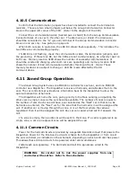
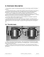
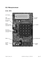
Confirm that the termination jumpers have been installed to connect the termination
resistors. These are two small jumpers just below the Group Communication Connector
block in the upper left corner of the CPU. (Refer to the diagram of the CPU)
Connect the communication cable (twisted pair in shield) from the Group Communication
Connector block of one car to the other car. The drain wire (or shield if no drain wire)
should be connected to the “G” (g
round) terminal of the Group Communication Connector
block on
one car only
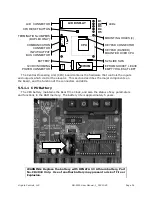
. See picture on page 26.
When both cars are in operation, the LED D4 should flash repeatedly. This indicates the
two CPUs are communicating properly.
If LED D4 is not flashing, check the communication cable, the termination jumpers, and
the grounding. If these look OK, but the CPUs are not communicating, do a factory reset on
both cars. Memory location 3188 shows the number of successful communications (it
should be constantly changing when both cars are operating) and memory location 3189
shows the number of bad communication attempts (this should be 0). (Note: These
memory locations are subject to change.) LED D4 is also affected by the I/O
communications.
4.11
Zoned Group Operation
The Zoned Group System uses one MH3000 controller for each car, and one MH3000
controller as a Dispatcher. The Dispatcher receives all hall calls, and allocates them to the
cars. The car controllers provide status information back to the Dispatcher to allow the
optimum allocation of hall calls.
The Dispatcher will home the cars, giving priority to the Main Landing, and putting the
other cars in empty zones as the cars become available. The number of zones is equal to
the number of cars. Each zone will have a car selected as the “Next” car in that zone. As
hall calls are entered, the “Next” car for the zone that the hall call is in will be assigned the
call. If another car is moving through the zone, or is at the floor where the call was
registered, then it will be assigned the call. Any car can cancel a hall call if it answers the
call.
If a zone is empty, then an idle car will be sent to that zone. If a call is registered in an
empty zone, a car in an adjacent zone will be assigned the call.
4.11.1
Common Circuits
Power for the hall call circuits is provided by a separate fused disconnect that powers the
Dispatcher. Power for the Fire Service circuits is taken from the Dispatcher or from one of
the car controllers, as indicated on the schematic, depending on which controller has power.
This allows these critical circuits to be powered under all circumstances.
Install each car separately. The Hall Calls and Hall Fire signals are wired to the
Dispatcher.
WARNING: Be careful not to mix the power supplies from one
controller with another. Refer to the schematic.


