Virginia Controls, LLC
MH-3000 User Manual, 1_03C10-VC
Page 34
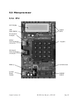
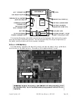
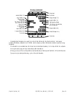
The Central Processing Unit (CPU) board contains the hardware that controls the inputs
and outputs which control the elevator. This section describes the major components on
the board, and the function of the connectors and LEDs.
5.5.1.1
CPU Battery
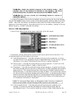
The CPU battery maintains the Real Time Clock, and also the status of key parameters
and functions in the RAM memory. The battery life is approximately 5 years.
WARNING: Replace the battery with RENATA 3V Lithium battery, Part
No. CR2032 Only. Use of another battery may present a risk of Fire or
Explosion.
CPU
LCD DISPLAY
DISPLAY
D1
D2
D3
D4
D5
+
-
G
-
+
D
:\
EPROM
INPUT/OUTPUT
BUS CONNECTOR
LEDs
KEYPAD CONNECTOR
KEYPAD (DASHED)
MOUNTED OVER CPU
COMMUNICATION
CONNECTOR
TERMINATION JUMPERS
(DUPLEX ONLY)
EPROM SOCKET, LEAVE
EMPTY HOLES AT LEFT
CPU RESET BUTTON
12VDC INCOMING
POWER CONNECTOR
BATTERY
CHIP
LCD CONNECTOR
S2 SLIDE SWS
MOUNTING HOLES (4)
+
D
:\


