Section 8
—
Setup Menu
MCP-25/MS
Valco Cincinnati
8-7
MC051 (July 2002)
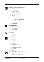
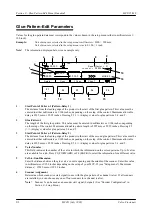
Encoder Configuration Parameters
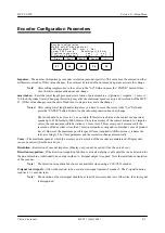
Impulses
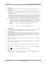
—The number of impulses per encoder revolution (encoder-specific). This value must be entered in either
millimeters or inches. If this value changes, the unit must be turned off and turned on again to activate the change.
Note!
After setting impulses, move the cursor to the “Set” field and press the “ENTER” button. Other-
wise, the ratio compensation does not change.
mm (inches)
—Enter the travel length per encoder revolution of parent machine. (Optimum: 1 impulse = 1 mm or 1/
100 inch of product travel) Changing this setting may alter the maximum speed capacity and resolution of the MCP-
25. (If this value changes, turn the unit off and turn it on again to activate the change.)
Notes!
After setting travel length and/or impulses, you have to move the cursor to the “Set” field and
press the “ENTER” button. Otherwise, the ratio compensation does not change.
The ratio should be as close to 1:1 as possible. If this ratio is obtained, the control can operate at
speeds up to 6500 feet/min (2000 m/min). Since the accuracy of the control amounts to 1 impulse
or less, the maximum possible deviation is 1 mm or less. This accuracy can be increased if the
resolution of the encoder is less than 1 mm (one impulse corresponds to less than 1 mm of product
travel). However, the maximum possible speed (Vmax) required with this accuracy reduces the
ratio accordingly. The Vmax parameter and the resolution change automatically.
Vmax
—The maximum speed at which the accuracy and resolution of the encoder are maintained. (Display only,
cannot be edited.) (See the note above.)
Resolution
—Resolution of encoder impulses. (Display only, cannot be edited.) (See the note above.)
Direction recognition
—If the direction recognition function is activated, gluing is only possible in one direction for
the parent machine. Additionally, an encoder with an A+B signal output is required. Note the installation orientation
of the encoder.
Note
! The direction recognition function is not available when using a VCE/VLD encoder.
Z-signal (start signal)
—Allows the encoder to be used as a start signal instead of scanner 5. The Z-signal function
requires a 1:1 encoder ratio.
Note
! The duration of the start signal should be at least 10 microseconds (ms). Otherwise, the start signal
is disregarded.
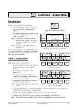
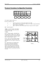
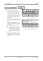
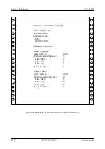
Encode r conf igurati on
Modi fy onl y at m ac hine stop !
00 01 I mpul ses = 0001 m m -> Set
Vmax= 2000 m/m in , Resolut ion=1. 00 m m
D i rectio n r ecogni ti on
:
yes [ ]
no [ ]
Z-S ignal on Sc anner 5 :
yes [ ]
no [ ]
F1
F2
F3
F4
F5
Pres.
Sensor
>>>
Enc 1.
Enc 2.
Содержание MCP-25/MS
Страница 1: ...MCP 25 MS Control Manual Number MC051 Release Date June 2004 ...
Страница 25: ......
Страница 27: ......
Страница 28: ......
Страница 29: ...3 4 5 1 2 2 4 5 3 1 ...
Страница 30: ......
Страница 31: ......
Страница 33: ...4 8 12 11 10 9 6 7 5 3 2 1 ...
Страница 34: ...3 7 9 10 8 5 6 4 1 2 1 4 3 2 ...
Страница 35: ...1 3 4 2 ...
Страница 36: ...7 9 10 8 3 5 6 4 1 2 ...
Страница 37: ...SHD NPN 5 4 3 24V Low Level Detector 0V 1 2 ...
Страница 38: ......
Страница 39: ......
Страница 40: ......
Страница 41: ......
Страница 42: ......
Страница 43: ...3 4 5 6 2 3 1 5 6 4 1 2 ...
Страница 44: ......
Страница 45: ......
Страница 46: ......
Страница 47: ......
Страница 48: ......
Страница 49: ...RODUCT 7 10 9 8 3 5 6 4 1 2 8 10 9 2 5 7 6 3 4 1 ...
Страница 50: ......
Страница 51: ......
Страница 52: ...6 8 10 9 7 1 3 5 4 2 ...
Страница 53: ......
Страница 54: ......
Страница 55: ...6 8 10 9 7 1 3 5 4 2 ...
Страница 56: ...VA LC O CI NCIN NA TI INC 513 87 4 6550 5 13 87 4 6550 VALC O C INCIN NATI INC ...
Страница 57: ......
Страница 58: ......
Страница 59: ......
Страница 60: ......
Страница 61: ......
Страница 62: ......
Страница 87: ......
Страница 99: ...F1 F2 F3 F4 F5 ...

