Section 16
—
Troubleshooting
MCP-25/MS
Valco Cincinnati
16-4
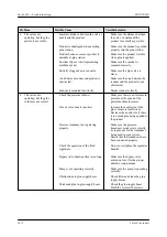
Problem
Possible Cause
Possible Solution
7. The valves
apply glue only
when the parent
machine
operates above
a certain speed.
Incorrect “Vmin”
(minimum threshold speed)
entered
Improper pressure-table(s)
Make sure the “Vmin” has been entered correctly
(setup menu).
Make sure the pressure table(s) are correct.
Increase the minimum-speed pressure setting.
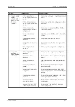
8. The glue
patterns shift or
disappear as the
speed of the
parent machine
increases.
Incorrect “Ton” and “Toff”
values entered
Improper “Tmin” setting
entered
Improper pressure-table(s)
Make sure the “Ton” and “Toff” values have been
entered correctly.
Increase the “Tmin” (setup menu) until the patterns
reappear. (The patterns may become longer at
slower speed when the Tmin is increased.)
Make sure the pressure table(s) are correct. Check
the pressure table(s) for extreme pressure
variations as machine speed changes.
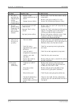
9. Only some of
the valves are
operating.
Valve not enabled
Check the scanner
assignment(s) (glue -pattern -
edit menu).
Check the encoder
assignment(s) (setup menu).
Check the valve cable
connections.
Incorrect glue mode for
valve in question
Make sure the valve -selection button on the front
panel has been pressed. (A LED on the button will
illuminate when a valve has been selected.)
Check the scanner assignment(s) (glue-pattern -
edit menu).
Check the encoder assignment(s) (setup menu).
Check the valve cable connections.
Make sure the glue mode is correct for the valve in
question (setup menu).
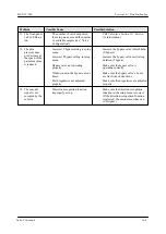
10. The valves
rema in on
continuously.
Control not in “AUTO”
mode.
Glue pattern entered
incorrectly
Glue mode incorrect
Valve faults (indicated by a
red LED on the valve-
selection button on the front
panel)
Make sure the control is in the proper mode
(“MAN” or “AUTO”). The valves will activate
continuously in the “MAN” mode.
Make sure the glue pattern lengths have been
entered correctly (glue-pattern -edit menu).
Check the glue mode (glue-pattern-edit menu).
Check for valve faults, which are indicated by a
red LED on the valve -selection button (left side of
front panel).
Содержание MCP-25/MS
Страница 1: ...MCP 25 MS Control Manual Number MC051 Release Date June 2004 ...
Страница 25: ......
Страница 27: ......
Страница 28: ......
Страница 29: ...3 4 5 1 2 2 4 5 3 1 ...
Страница 30: ......
Страница 31: ......
Страница 33: ...4 8 12 11 10 9 6 7 5 3 2 1 ...
Страница 34: ...3 7 9 10 8 5 6 4 1 2 1 4 3 2 ...
Страница 35: ...1 3 4 2 ...
Страница 36: ...7 9 10 8 3 5 6 4 1 2 ...
Страница 37: ...SHD NPN 5 4 3 24V Low Level Detector 0V 1 2 ...
Страница 38: ......
Страница 39: ......
Страница 40: ......
Страница 41: ......
Страница 42: ......
Страница 43: ...3 4 5 6 2 3 1 5 6 4 1 2 ...
Страница 44: ......
Страница 45: ......
Страница 46: ......
Страница 47: ......
Страница 48: ......
Страница 49: ...RODUCT 7 10 9 8 3 5 6 4 1 2 8 10 9 2 5 7 6 3 4 1 ...
Страница 50: ......
Страница 51: ......
Страница 52: ...6 8 10 9 7 1 3 5 4 2 ...
Страница 53: ......
Страница 54: ......
Страница 55: ...6 8 10 9 7 1 3 5 4 2 ...
Страница 56: ...VA LC O CI NCIN NA TI INC 513 87 4 6550 5 13 87 4 6550 VALC O C INCIN NATI INC ...
Страница 57: ......
Страница 58: ......
Страница 59: ......
Страница 60: ......
Страница 61: ......
Страница 62: ......
Страница 87: ......
Страница 99: ...F1 F2 F3 F4 F5 ...

