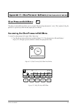
Appendix C
—
Glue-Pressure Software (Older Generation Controls)
MCP-25/MS
Valco Cincinnati
C-3
Creating a Glue-Pressure
Curve
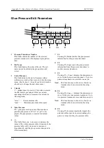
To create a glue-pressure curve, follow these steps:
1. Using either the F3 ( ) or
F4 ( ) keys, select the pressure
transducer (1 or 2) that you want to
program. The selected pressure-transducer
number displays in the top left part of the
screen next to the pressure-regulator
symbol.
Note!
Up to two independent pressure
transducers can be used.
2. Determine the glue pressure (see “Ex-
amples of Glue-Pressure Values” below).
Note!
The maximum (100%) output
pressure of the pressure transducer
amounts to 72 psi (6 bar) air pressure.
This output air pressure can work
with the following:
Step 1
—
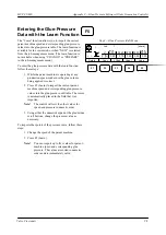
Glue-Pressure-Edit Menu
Job:
1
[m/min]
0000 0020 0300 0000 000 0
+ / -
1
m i n.
ma x.
005 010 090 000 000
V
P [%]
F1
F2
F3
F4
F5
•
1:1 ratio
—Direct from a pressure container, a 1:1 membrane pump (DD-1 pump), or a 1:1 glue-pressure
regulator (flow control)
•
Larger speed increase/decrease ratio
—A pump with speed increase/decrease ratio (example: 2:1, 5:1,
7:1, 10:1) or a glue-pressure regulator (flow control) with speed increase/decrease ratio (example: 2:1,
5:1, 7:1, 10:1).
3. Enter the glue-pressure data into the glue-pressure table.
Notes!
The glue-pressure data can be entered either manually or with the Learn function (see the following
pages for procedures). The information entered into the glue-pressure table creates the glue-pressure
curve.
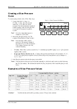
Examples of Glue-Pressure Values
Attention
!
Note the maximum allowable operation pressure of the pressure container.
Delete
Copy
Chan.
Chan.
+^
Learn
^ -
Corresponding Glue Pressure – psi (bar)
Input in %
Pressure Transducer
Air-Pressure Output –
psi (bar)
1:1
2:1
3:1
5:1
7:1
10:1
100
72 (6)
72 (6)
160 (12)
246 (18)
420 (30)
594 (42)
75
51 (4.5)
51 (4.5)
116 (9)
181 (13.5)
312 (22.5)
442 (31.5)
683 (45)
50
29 (3)
29 (3)
72 (6)
116 (9)
203 (15)
290 (21)
420 (30)
25
7 (1.5)
7 (1.5)
29 (3)
51 (4.5)
94 (7.5)
138 (10.5)
203 (15)
5
0 (0.3)
0 (0.3)
0 (0.6)
0 (0.9)
7 (1.5)
16 (2.1)
29 (3)
Chan.
^ -
+ Chan.
^
Содержание MCP-25/MS
Страница 1: ...MCP 25 MS Control Manual Number MC051 Release Date June 2004 ...
Страница 25: ......
Страница 27: ......
Страница 28: ......
Страница 29: ...3 4 5 1 2 2 4 5 3 1 ...
Страница 30: ......
Страница 31: ......
Страница 33: ...4 8 12 11 10 9 6 7 5 3 2 1 ...
Страница 34: ...3 7 9 10 8 5 6 4 1 2 1 4 3 2 ...
Страница 35: ...1 3 4 2 ...
Страница 36: ...7 9 10 8 3 5 6 4 1 2 ...
Страница 37: ...SHD NPN 5 4 3 24V Low Level Detector 0V 1 2 ...
Страница 38: ......
Страница 39: ......
Страница 40: ......
Страница 41: ......
Страница 42: ......
Страница 43: ...3 4 5 6 2 3 1 5 6 4 1 2 ...
Страница 44: ......
Страница 45: ......
Страница 46: ......
Страница 47: ......
Страница 48: ......
Страница 49: ...RODUCT 7 10 9 8 3 5 6 4 1 2 8 10 9 2 5 7 6 3 4 1 ...
Страница 50: ......
Страница 51: ......
Страница 52: ...6 8 10 9 7 1 3 5 4 2 ...
Страница 53: ......
Страница 54: ......
Страница 55: ...6 8 10 9 7 1 3 5 4 2 ...
Страница 56: ...VA LC O CI NCIN NA TI INC 513 87 4 6550 5 13 87 4 6550 VALC O C INCIN NATI INC ...
Страница 57: ......
Страница 58: ......
Страница 59: ......
Страница 60: ......
Страница 61: ......
Страница 62: ......
Страница 87: ......
Страница 99: ...F1 F2 F3 F4 F5 ...

