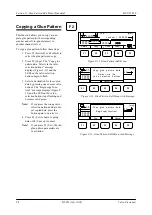
Section 9
—
Glue-Pattern-Edit Menu (Standard)
MCP-25/MS
Valco Cincinnati
9-2
MC051 (July 2002)
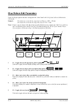
Glue-Pattern-Edit Parameters
Values for the glue-pattern data must correspond to the values chosen in the setup menu (either in millimeters or 1/
100 inch).
Example:
Unit of measure selected in the setup menu is millimeters:
0100 = 100 mm
Unit of measure selected in the setup menu is inch:
01.00 = 1 inch
Note!
The information displayed below is an example only.
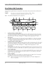
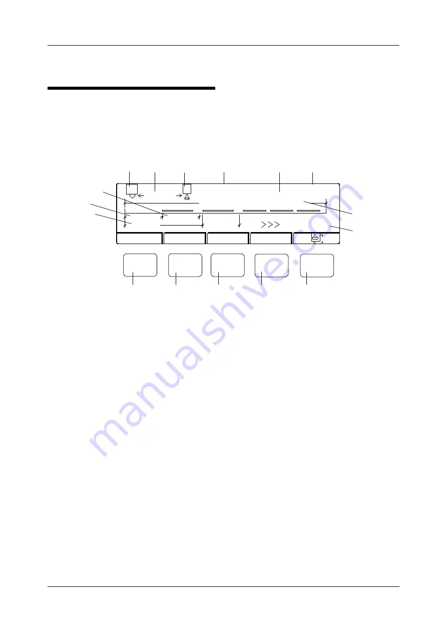
1
Start Point of Pattern 1 (Pattern-Delay 1)
The distance from the leading edge of the product to the start of the first glue pattern. This value must be
entered in either millimeters or 1/100 inches, depending on the setup of the control. Maximum allowable
delay is 9999 mm or 99.99 inches. Pressing F5 (>>>) displays values for glue patterns 3, 4, and 5.
2
Glue-Pattern 1
The length of the first glue pattern. This value must be entered in millimeters or 1/100 inches, depending
on the setup of the control. Maximum allowable pattern length is 9999 mm or 99.99 inches. Pressing F5
(>>>) displays values for glue patterns 3, 4 and 5.
3
Start Point of Pattern 2 (Pattern-Delay 2)
The distance from the leading edge of the product to the start of the second glue pattern. This value must be
entered in either millimeters or 1/100 inches, depending on the setup of the control. Maximum allowable
delay is 9999 mm or 99.99 inches. Pressing F5 (>>>) displays values for glue patterns 3, 4, and 5.
4
Valve Number
This field indicates the number of the valve to which the information on the screen pertains. Up to 8 valves
are available for a job. Press F3 (FORWARD) or F4 (BACK) to select the information for a different valve.
5
Cell-to-Gun Dimension
Enter the distance between the glue valve’s nozzle opening and the middle of the scanner. Enter this value
in millimeters or 1/100 inches depending on the setup of your MCP-25 (see “Setup menu”). Maximum
distance = 19999 mm or 199.99 inches.
6
Scanner Assignment
Determine which scanner (or start signal) to use with the glue pattern of a channel (valve). If all scanners
are installed, you can choose any one of four scanners for a channel (valve).
Note
! Scanner 5 can be used as an encoder start signal (0 signal). (See “Encoder Configuration” in
Section 8—Setup Menu.
)
11
2
4
10
Delete
Copy
F1
F2
F3
F4
F5
1
1
00000
00000
00000
00000
00000
Job:
1
[mm]
Lockout = 0 00000
MODE 0
16
5
6
7
8
9
12
13
14
15
1
Repeat factor = 01
3
+ Chan.
^
^
Chan. -
Содержание MCP-25/MS
Страница 1: ...MCP 25 MS Control Manual Number MC051 Release Date June 2004 ...
Страница 25: ......
Страница 27: ......
Страница 28: ......
Страница 29: ...3 4 5 1 2 2 4 5 3 1 ...
Страница 30: ......
Страница 31: ......
Страница 33: ...4 8 12 11 10 9 6 7 5 3 2 1 ...
Страница 34: ...3 7 9 10 8 5 6 4 1 2 1 4 3 2 ...
Страница 35: ...1 3 4 2 ...
Страница 36: ...7 9 10 8 3 5 6 4 1 2 ...
Страница 37: ...SHD NPN 5 4 3 24V Low Level Detector 0V 1 2 ...
Страница 38: ......
Страница 39: ......
Страница 40: ......
Страница 41: ......
Страница 42: ......
Страница 43: ...3 4 5 6 2 3 1 5 6 4 1 2 ...
Страница 44: ......
Страница 45: ......
Страница 46: ......
Страница 47: ......
Страница 48: ......
Страница 49: ...RODUCT 7 10 9 8 3 5 6 4 1 2 8 10 9 2 5 7 6 3 4 1 ...
Страница 50: ......
Страница 51: ......
Страница 52: ...6 8 10 9 7 1 3 5 4 2 ...
Страница 53: ......
Страница 54: ......
Страница 55: ...6 8 10 9 7 1 3 5 4 2 ...
Страница 56: ...VA LC O CI NCIN NA TI INC 513 87 4 6550 5 13 87 4 6550 VALC O C INCIN NATI INC ...
Страница 57: ......
Страница 58: ......
Страница 59: ......
Страница 60: ......
Страница 61: ......
Страница 62: ......
Страница 87: ......
Страница 99: ...F1 F2 F3 F4 F5 ...

