75
RTAA-IOM-3
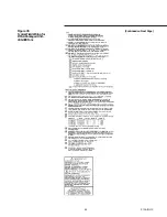
Installation Check List
Complete this checklist as the unit is
installed, to verify that all
recommended procedures are
accomplished before the unit is started.
This checklist does not replace the
detailed Instructions given in the
“Installation -Mechanical” and
“Installation -Electrical” sections of this
manual. Read both sections
completely, to become familiar with the
installation procedures, prior to
beginning the work.
Receiving
[ ] Verify that the unit nameplate data
corresponds to the ordering
information.
[ ] Inspect the unit for shipping
damage and any shortages of
materials. Report any damage or
shortage to the carder.
Unit Location and Mounting
[ ] Inspect the location desired for
installation and verify adequate
service access clearances.
[ ] Provide drainage for evaporator
water.
[ ] Remove and discard all shipping
materials (cartons, etc.)
[ ] Install optional spring isolators, if
required.
[ ] Level the unit and secure it to the
mounting surface.
Unit Piping
[ ] Flush all unit water piping before
making final connections to the unit.
Caution: If using an acidic
commercial flushing solution,
construct a temporary bypass
around the unit to prevent damage
to internal components of the
evaporator.
Caution: To avoid possible
equipment damage, do not use
untreated or improperly treated
system water.
[ ] Connect the chilled water piping to
the evaporator.
[ ] Install pressure gauges and shutoff
valves on the chilled water inlet and
outlet to the evaporator.
[ ] Install a water strainer in the
entering chilled water line.
[ ] Install a balancing valve and flow
switch (discretionary) in the leaving
chilled water line.
[ ] Install a drain with shutoff valve or a
drain plug on the evaporator.
[ ] Vent the chilled water system at
high points in the system piping.
[ ] Apply heat tape and insulation, as
necessary, to protect all exposed
piping from freeze-up.
Electrical Wiring
WARNING: To prevent injury or
death, disconnect electrical
power source before completing
wiring connections to the unit.
Caution: To avoid corrosion and
overheating at terminal
connections, use copper
conductors only.
[ ] Connect the unit power supply
wiring with fused-disconnect to the
terminal block (or unit-mounted
disconnect) in the power section of
the control panel.
[ ] Connect the control power supply
wiring with fused-disconnect to the
terminal strip in the power section
of the control panel.
[ ] Connect power supply wiring to the
evaporator heat tape. Connect leads
551 and 552 to terminals 11 and 12
of terminal strip 1TB3.
[ ] Connect power supply wiring to the
chilled water pump.
[ ] Connect power supply wiring to any
auxiliary heat tapes.
[ ] Connect the auxiliary contact of the
chilled water pump (5K1) in series
with the optional flow switch, if
installed, and then connect to the
proper terminals.
[ ] For the External Start/Stop function,
install wiring from remote contacts
(5K5, 5K21) to the proper terminals
on terminal strip 1U1TB3.
Caution: Information in
Interconnecting Wiring: Chilled
Water Pump Interlock and External
Auto/Stop must be adhered to or
equipment damage may occur.
[ ] If the remote alarm/running/
maximum capacity contacts are
used, install leads 525 thru 532 from
the panel to the proper terminals on
terminal strip 1U1TB4.
[ ] If the emergency stop function is
used, install low voltage leads 513
and 514 to terminals 3 and 4 of
1U1TB1.
[ ] If indoor zone temperature is to be
used, install leads 501 and 502 on
6RT4 to the proper terminals on
1U2TB1.
[ ] If the ice making-option is used,
install leads 501 and 502 on 5K20 to
the proper terminals on 1U2TB1.
Содержание RTAA-130
Страница 2: ... American Standard Inc 1991 ...
Страница 8: ...8 RTAA IOM 3 ...
Страница 13: ...13 RTAA IOM 3 Figure 3 Typical RTAA Packaged Unit 240 400 Tons Control Panel Evaporator Outlet Inlet ...
Страница 24: ...24 RTAA IOM 3 ...
Страница 26: ...26 RTAA IOM 3 Figure 9 Dimensions and Clearances for RTAA Packaged Unit 130 to 200 Ton RTAA SU 1000E ...
Страница 27: ...27 RTAA IOM 3 Figure 10 Dimensions and Clearances for RTAA Packaged Unit 240 300 Ton RTAA SU 1001C ...
Страница 28: ...28 RTAA IOM 3 Figure 11 Dimensions and Clearances for RTAA Packaged Unit 340 to 400 Ton RTAA SU 1002C ...
Страница 38: ...38 RTAA IOM 3 RTAA SA 2002C Figure 19 Spring Isolator Placement for Typical RTAA Packaged Unit 240 400 Tons ...
Страница 46: ...46 RTAA IOM 3 Figure 24 Typical Domestic Water Heater Piping Figure 25 Typical Domestic Water Heater Piping ...
Страница 50: ...50 RTAA IOM 3 Figure 30 Refrigerant Circuit Identification ...
Страница 52: ...52 RTAA IOM 3 Figure 31 Remote Evaporator Piping Example ...
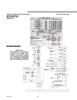
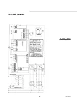
Страница 58: ...58 RTAA IOM 3 Continued on Next Page Figure 34 Typical Field Wiring for RTAA Packaged Unit 130 to 200 Tons ...
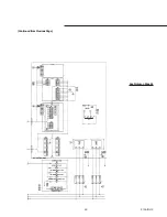
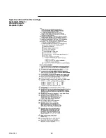
Страница 59: ...59 RTAA IOM 3 Continued from Previous Page See Notes on Next Page ...
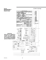
Страница 61: ...61 RTAA IOM 3 Figure 35 Typical Field Wiring for RTAA Packaged Unit 240 400 Tons Continued on Next Page ...
Страница 63: ...63 RTAA IOM 3 Continued from Previous Page See Notes on Page 61 ...
Страница 64: ...64 RTAA IOM 3 Figure 36 Typical Field Wiring for RTAA With Remote Evaporator Option Continued on Next Page ...
Страница 65: ...65 RTAA IOM 3 Continued from Previous Page See Notes on Page 61 ...
Страница 76: ...76 RTAA IOM 3 ...
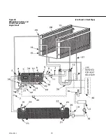
Страница 78: ...78 RTAA IOM 3 Figure 40 Refrigeration System and Control Components Single Circuit Continued on Next Page ...
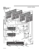
Страница 80: ...80 RTAA IOM 3 Figure 41 Refrigeration System and Control Components Duplex Circuit Continued on Next Page ...
Страница 92: ...92 RTAA IOM 3 Figure 51 Operator Interface Controls ...
Страница 120: ...120 RTAA IOM 3 ...
Страница 126: ...126 RTAA IOM 3 Figure 56 Unit Sequence of Operation RTAA 240 to 400 Tons Continued on Next Page ...
Страница 127: ...127 RTAA IOM 3 Continued from Previous Page 2307 1566C ...
Страница 128: ...128 RTAA IOM 3 Figure 57 Unit Sequence of Operation RTAA 130 to 200 Tons 2306 9122A ...
Страница 132: ...132 RTAA IOM 3 Figure 58 Operator s Log ...
Страница 138: ...138 RTAA IOM 3 ...

