111
RTAA-IOM-3
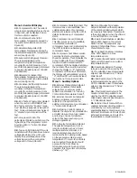
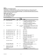
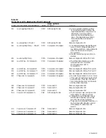
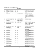
Table 18
Diagnostics and Troubleshooting Chart (Continued)
DIAG. ACTIVE
CODE DIAGNOSTIC DESCRIPTION
TYPE
MODES
CAUSE
NONE Outdoor Air Temperature
None
All
Open or Short
Sensor (Both Outdoor Air
a. Display dashes e.g. 14 - - - - -”,
Reset or Low Ambient Lockout
Not Selected)
Ab
Evap. Leaving Water Temp. Sensor
MMR
All
Open or Short
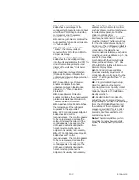
bA
Overload Trip - Compressor A
CMR
Compressor Energized Compressor current exceeded overload
time vs. trip characteristic.
bb
Overload Trip - Compressor B
CMR
Compressor Energized Compressor current exceeded overload
time vs. trip characteristic.
bC
Overload Trip - Compressor C
CMR
Compressor Energized Compressor current exceeded overload
time vs. trip characteristic.
bd
Overload Trip - Compressor D
CMR
Compressor Energized Compressor current exceeded overload
time vs. trip characteristic.
bE
High Pressure Cutout - Compressor C
CMR
All
a. A high pressure cutout was detected on
Compressor C; trip at 405 + or - 7 PSIG.
BF
High Pressure Cutout - Compressor D
CMR
All
a. A high pressure cutout was detected on
Compressor D; trip at 405 + or - 7 PSIG.
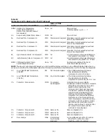
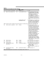
NONE CWS/Leaving Water Temp.
None
All
No diagnostic, display to flash and
Cutout Setpoint Overlap
limit value to last legal value.
NOTE
: The above is not a diagnostic because you don’t want the display vectoring you to a different display state when you
are trying to set either the chilled water setpoint or the leaving water temp. cutout setpoint as it will in the case of a diagnostic.
C5
Low Chilled Water Temperature
IFW
No Circuits Energized
a. The chilled water temp. fell below
(Unit Off)
the cutout setpoint while the
compressors were not running.
C6
Low Chilled Water Temperature
MAR
Any Circuit Energized
a. The chilled water temp. fell below
(Unit On)
the cutout setpoint while the
compressors were running for 30 F - sec.
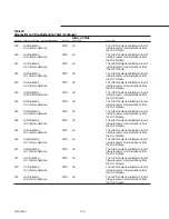
CA
Contactor - Compressor A
MMR
Compressor
a. Welded compressor contactor.
Not Energized
b. Detected a welded compressor contactor
off but the current does not go to zero.
Detection time shall be 5 second
minimum and 10 seconds maximum.
On detection, generate the diagnostic,
energize the appropriate alarm relay,
continue to command the affected
compressor off, energize the affected
compressors oil line solenoid, stop all
other compressors, unload the running
compressor with the welded contactor,
open the EXV to it’s maximum open
position, and continue to do fan control.
Do not exit this condition until the
controller is manually reset.
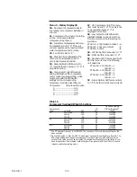
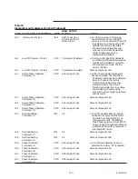
Cb
Contactor - Compressor B
MMR
Same as CA
Same as diagnostic CA
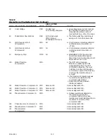
CC
Contactor - Compressor C
MMR
Same as CA
Same as diagnostic CA
Cd
Contactor - Compressor D
MMR
Same as CA
Same as diagnostic CA
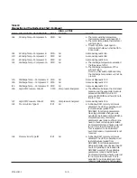
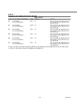
d7
Over Voltage
MAR
Pre-start and
a. Line voltage above +10% of nominal.
Any Circuit(s)
(Must hold = +10% of nominal.
Energized
Must trip = +15% of nominal.)
Содержание RTAA-130
Страница 2: ... American Standard Inc 1991 ...
Страница 8: ...8 RTAA IOM 3 ...
Страница 13: ...13 RTAA IOM 3 Figure 3 Typical RTAA Packaged Unit 240 400 Tons Control Panel Evaporator Outlet Inlet ...
Страница 24: ...24 RTAA IOM 3 ...
Страница 26: ...26 RTAA IOM 3 Figure 9 Dimensions and Clearances for RTAA Packaged Unit 130 to 200 Ton RTAA SU 1000E ...
Страница 27: ...27 RTAA IOM 3 Figure 10 Dimensions and Clearances for RTAA Packaged Unit 240 300 Ton RTAA SU 1001C ...
Страница 28: ...28 RTAA IOM 3 Figure 11 Dimensions and Clearances for RTAA Packaged Unit 340 to 400 Ton RTAA SU 1002C ...
Страница 38: ...38 RTAA IOM 3 RTAA SA 2002C Figure 19 Spring Isolator Placement for Typical RTAA Packaged Unit 240 400 Tons ...
Страница 46: ...46 RTAA IOM 3 Figure 24 Typical Domestic Water Heater Piping Figure 25 Typical Domestic Water Heater Piping ...
Страница 50: ...50 RTAA IOM 3 Figure 30 Refrigerant Circuit Identification ...
Страница 52: ...52 RTAA IOM 3 Figure 31 Remote Evaporator Piping Example ...
Страница 58: ...58 RTAA IOM 3 Continued on Next Page Figure 34 Typical Field Wiring for RTAA Packaged Unit 130 to 200 Tons ...
Страница 59: ...59 RTAA IOM 3 Continued from Previous Page See Notes on Next Page ...
Страница 61: ...61 RTAA IOM 3 Figure 35 Typical Field Wiring for RTAA Packaged Unit 240 400 Tons Continued on Next Page ...
Страница 63: ...63 RTAA IOM 3 Continued from Previous Page See Notes on Page 61 ...
Страница 64: ...64 RTAA IOM 3 Figure 36 Typical Field Wiring for RTAA With Remote Evaporator Option Continued on Next Page ...
Страница 65: ...65 RTAA IOM 3 Continued from Previous Page See Notes on Page 61 ...
Страница 76: ...76 RTAA IOM 3 ...
Страница 78: ...78 RTAA IOM 3 Figure 40 Refrigeration System and Control Components Single Circuit Continued on Next Page ...
Страница 80: ...80 RTAA IOM 3 Figure 41 Refrigeration System and Control Components Duplex Circuit Continued on Next Page ...
Страница 92: ...92 RTAA IOM 3 Figure 51 Operator Interface Controls ...
Страница 120: ...120 RTAA IOM 3 ...
Страница 126: ...126 RTAA IOM 3 Figure 56 Unit Sequence of Operation RTAA 240 to 400 Tons Continued on Next Page ...
Страница 127: ...127 RTAA IOM 3 Continued from Previous Page 2307 1566C ...
Страница 128: ...128 RTAA IOM 3 Figure 57 Unit Sequence of Operation RTAA 130 to 200 Tons 2306 9122A ...
Страница 132: ...132 RTAA IOM 3 Figure 58 Operator s Log ...
Страница 138: ...138 RTAA IOM 3 ...

