96
RTAA-IOM-3
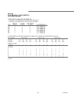
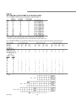
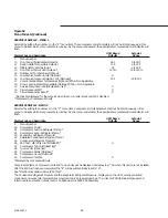
Figure 52
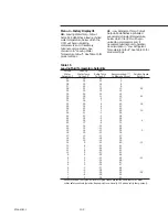
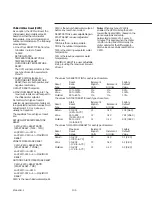
Menu Formats (Continued)
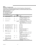
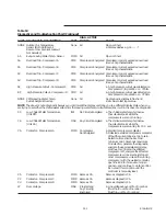
FACTORY DISPLAY #1 - MENU 4
Caution: Do not leave unit unattended while in Menu 4 or 5. Inadvertent unit safety setpoint changes could occur.
Selected by setting the number 4 in the “P” menu item. Unlike menus 0 through 3, the number 4 can only be set by entering a
combination of numbers. This combination consists of a sequence of “P” menu numbers -0, 1, 2, 1, 2, 3, 2, 3. 4.
Compressor/circuit indicators will not be lit continuously in this menu to indicate which compressors are running. As the
menu is advanced the appropriate compressor/circuit indicator will flash.
UCM Based
Setpoint
Display Code and Description
Defaults
Range
P
Menu Number
40
Leaving water Temp. Cutout Setpoint
35 F
-10 to 35 F
41
Low Refrigerant Temp. Cutout Setpoint
22 F
-39 to 35 F
42
Condenser Limit Setpoint - % HPC
90%
80 to 120%
43
Lead/Lag - d/E
E
44
SI Display Units - d/E
d
45
Unit Line Voltage*
460 V
46
Under/Over Voltage Protection - d/E
d
47
Phase Imbalance Protection d/E
E
48
Phase Reversal Protection d/E
E
49
Superheat Setpoint
8 F
4 to 20 F
4A
EXV Control Response Setpoint**
20
2 to 200
4b
LWT Control Response Setpoint
40
2 to 220
4C
ICS Address (Optional)
4d
Fan Control Deadband Bias**
0
-50 to +50
4E
Programmable Relay Setup
1
1 to 12
(see Alarm/Running/Maximum Capacity Contact Outputs)
4F
Restart Inhibit Timer
120 sec.
30 to 120 sec.
*Entry will be selected from 200, 220, 230, 346, 380, 415, 460, 500 or 575 volts. Dashes will be displayed if the Under/Over
Voltage Protection option is not installed.
**Displayed by circuit.
Содержание RTAA-130
Страница 2: ... American Standard Inc 1991 ...
Страница 8: ...8 RTAA IOM 3 ...
Страница 13: ...13 RTAA IOM 3 Figure 3 Typical RTAA Packaged Unit 240 400 Tons Control Panel Evaporator Outlet Inlet ...
Страница 24: ...24 RTAA IOM 3 ...
Страница 26: ...26 RTAA IOM 3 Figure 9 Dimensions and Clearances for RTAA Packaged Unit 130 to 200 Ton RTAA SU 1000E ...
Страница 27: ...27 RTAA IOM 3 Figure 10 Dimensions and Clearances for RTAA Packaged Unit 240 300 Ton RTAA SU 1001C ...
Страница 28: ...28 RTAA IOM 3 Figure 11 Dimensions and Clearances for RTAA Packaged Unit 340 to 400 Ton RTAA SU 1002C ...
Страница 38: ...38 RTAA IOM 3 RTAA SA 2002C Figure 19 Spring Isolator Placement for Typical RTAA Packaged Unit 240 400 Tons ...
Страница 46: ...46 RTAA IOM 3 Figure 24 Typical Domestic Water Heater Piping Figure 25 Typical Domestic Water Heater Piping ...
Страница 50: ...50 RTAA IOM 3 Figure 30 Refrigerant Circuit Identification ...
Страница 52: ...52 RTAA IOM 3 Figure 31 Remote Evaporator Piping Example ...
Страница 58: ...58 RTAA IOM 3 Continued on Next Page Figure 34 Typical Field Wiring for RTAA Packaged Unit 130 to 200 Tons ...
Страница 59: ...59 RTAA IOM 3 Continued from Previous Page See Notes on Next Page ...
Страница 61: ...61 RTAA IOM 3 Figure 35 Typical Field Wiring for RTAA Packaged Unit 240 400 Tons Continued on Next Page ...
Страница 63: ...63 RTAA IOM 3 Continued from Previous Page See Notes on Page 61 ...
Страница 64: ...64 RTAA IOM 3 Figure 36 Typical Field Wiring for RTAA With Remote Evaporator Option Continued on Next Page ...
Страница 65: ...65 RTAA IOM 3 Continued from Previous Page See Notes on Page 61 ...
Страница 76: ...76 RTAA IOM 3 ...
Страница 78: ...78 RTAA IOM 3 Figure 40 Refrigeration System and Control Components Single Circuit Continued on Next Page ...
Страница 80: ...80 RTAA IOM 3 Figure 41 Refrigeration System and Control Components Duplex Circuit Continued on Next Page ...
Страница 92: ...92 RTAA IOM 3 Figure 51 Operator Interface Controls ...
Страница 120: ...120 RTAA IOM 3 ...
Страница 126: ...126 RTAA IOM 3 Figure 56 Unit Sequence of Operation RTAA 240 to 400 Tons Continued on Next Page ...
Страница 127: ...127 RTAA IOM 3 Continued from Previous Page 2307 1566C ...
Страница 128: ...128 RTAA IOM 3 Figure 57 Unit Sequence of Operation RTAA 130 to 200 Tons 2306 9122A ...
Страница 132: ...132 RTAA IOM 3 Figure 58 Operator s Log ...
Страница 138: ...138 RTAA IOM 3 ...

