
93
RTAA-IOM-3
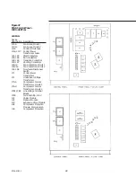
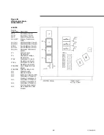
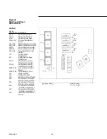
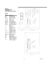
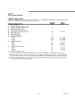
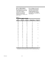
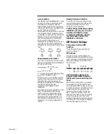
Figure 52
Menu Formats
OPERATING DISPLAY - MENU 0
Selected by setting the number 0 in the “P” menu item. Compressor/circuit
indicators will be lit Continuously in this menu to indicate which compressors/
circuits are running. All items of Menu 0 are display only. Setpoint changes must
be made in other menus.
Display Code and Description
P
Menu Number
A
Operating Code
b
Last Diagnostic Code
C
Other Diagnostic Codes
d
Active Chilled Water Setpoint*
E
Evaporator Entering Water Temperature
F
Evaporator Leaving Water Temperature
L
Active Current Limit Setpoint
*Dashes are displayed for the setpoint when the chiller is either in the
“Ice Building” or “Ice Building Complete” mode.
Menus
There are six menus, four of which are
shown on the operator interface panel
and two factory displays, which are
described later in this section. The
menus are numbered as follows:
Operating Display - Menu 0
Service #1 Display - Menu 1
Service #2 Display - Menu 2
Auxiliary Options Display - Menu 3
Factory Display - Menu 4
Factory Display - Menu 5
Each menu can be considered to be a
page of data, formatted as shown in
Figure 52. The operator can view one
line of the menu at a time (menu item)
on the digital display and can scroll
through the menu by using the Display
Up and Display Down keys. For
example, when the digital display
shows “P 0”, the UCM is in the
“Operating Display” menu. By
depressing the Display Down key one
time, the next line of the menu,
“Operating Code”, will be shown as an
“A”, along with the current unit
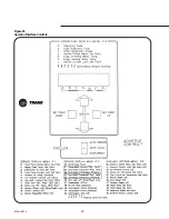
operating status. All operating and
diagnostic codes are described on the
“Condition Codes” label, as shown in
Figure 53.
There are a few exceptions to the
scrolling function. When a menu
selection represents multiple pieces of
information:
“C” Menu Item - Other Diagnostic
Codes”: When this menu item is
selected, depressing the Display Down
key will display diagnostic history in
code number sequence. Use the
Display Up key to return to the top of
the list. While in the “C” menu item,
flashing indicates that the information
is currently “true”, whereas steady, or
non-flashing indicates historic data
only. The digital display will not
advance to the next item (d) until all
diagnostics have been displayed. If
there are no diagnostics to display, the
data field will be blank for one key
stroke.
Compressor/Circuit Parameters:
Because the unit has two, three or four
compressors and two refrigerant
circuits, items that refer to compressors
or circuits will remain selected until
information for all have been
displayed. For example, assume a
“29”, “Compressor Starts”, menu
selection on a two compressor unit.
The menu numbered “29” will be
displayed and the indicator over the
“A” compressor will be flashing. By
depressing the Display Down key one
time, the “29” will remain but the
indicator light over the “B” compressor
will be flashing. Another Display Down
key stroke will display menu “2A”,
Compressor Hours, with compressor
“A” indicator flashing. If either the
Display Up or Display down keys are
held down, the scrolling will continue
until the key is released, or until
reaching the top or bottom of the
menu. In this case, the display will
return to the “P” menu position and
stop.
To change menus, scroll to the “P”
menu position and use the Set Point
Up or Set Point Down keys. For
example, assume that the display
shows “P 0” and it is desired to view
the Auxiliary Options on Menu 3.
Depress the Set Point Up key three
times and the “P 3” menu will be
displayed. To return to Menu 0, depress
the Set Point Down key three times or
Set Point Up key once (to wrap around)
and “P 0” will be displayed. This
procedure will work for menus 0
through 3.
A combination of key strokes is
required to access menus 4 and 5. With
the display in the “P” menu position
(P), use the Set Point Up and Down
keys to display “0, 1, 2, 1, 2, 3, 2, 3, 4”.
Once in the “P 4” menu, use the Set
Point Up key to access menu 5.
All menus are always accessible,
whether the unit is in a “running” or
‘stopped” mode.
Содержание RTAA-130
Страница 2: ... American Standard Inc 1991 ...
Страница 8: ...8 RTAA IOM 3 ...
Страница 13: ...13 RTAA IOM 3 Figure 3 Typical RTAA Packaged Unit 240 400 Tons Control Panel Evaporator Outlet Inlet ...
Страница 24: ...24 RTAA IOM 3 ...
Страница 26: ...26 RTAA IOM 3 Figure 9 Dimensions and Clearances for RTAA Packaged Unit 130 to 200 Ton RTAA SU 1000E ...
Страница 27: ...27 RTAA IOM 3 Figure 10 Dimensions and Clearances for RTAA Packaged Unit 240 300 Ton RTAA SU 1001C ...
Страница 28: ...28 RTAA IOM 3 Figure 11 Dimensions and Clearances for RTAA Packaged Unit 340 to 400 Ton RTAA SU 1002C ...
Страница 38: ...38 RTAA IOM 3 RTAA SA 2002C Figure 19 Spring Isolator Placement for Typical RTAA Packaged Unit 240 400 Tons ...
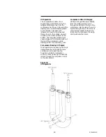
Страница 46: ...46 RTAA IOM 3 Figure 24 Typical Domestic Water Heater Piping Figure 25 Typical Domestic Water Heater Piping ...
Страница 50: ...50 RTAA IOM 3 Figure 30 Refrigerant Circuit Identification ...
Страница 52: ...52 RTAA IOM 3 Figure 31 Remote Evaporator Piping Example ...
Страница 58: ...58 RTAA IOM 3 Continued on Next Page Figure 34 Typical Field Wiring for RTAA Packaged Unit 130 to 200 Tons ...
Страница 59: ...59 RTAA IOM 3 Continued from Previous Page See Notes on Next Page ...
Страница 61: ...61 RTAA IOM 3 Figure 35 Typical Field Wiring for RTAA Packaged Unit 240 400 Tons Continued on Next Page ...
Страница 63: ...63 RTAA IOM 3 Continued from Previous Page See Notes on Page 61 ...
Страница 64: ...64 RTAA IOM 3 Figure 36 Typical Field Wiring for RTAA With Remote Evaporator Option Continued on Next Page ...
Страница 65: ...65 RTAA IOM 3 Continued from Previous Page See Notes on Page 61 ...
Страница 76: ...76 RTAA IOM 3 ...
Страница 78: ...78 RTAA IOM 3 Figure 40 Refrigeration System and Control Components Single Circuit Continued on Next Page ...
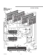
Страница 80: ...80 RTAA IOM 3 Figure 41 Refrigeration System and Control Components Duplex Circuit Continued on Next Page ...
Страница 92: ...92 RTAA IOM 3 Figure 51 Operator Interface Controls ...
Страница 120: ...120 RTAA IOM 3 ...
Страница 126: ...126 RTAA IOM 3 Figure 56 Unit Sequence of Operation RTAA 240 to 400 Tons Continued on Next Page ...
Страница 127: ...127 RTAA IOM 3 Continued from Previous Page 2307 1566C ...
Страница 128: ...128 RTAA IOM 3 Figure 57 Unit Sequence of Operation RTAA 130 to 200 Tons 2306 9122A ...
Страница 132: ...132 RTAA IOM 3 Figure 58 Operator s Log ...
Страница 138: ...138 RTAA IOM 3 ...


