20
RTAA-IOM-3
Warnings and Cautions
Warnings
and
Cautions
appear in
boldface
type at appropriate points in
this manual.
Warnings
are provided to alert
personnel to potential hazards that can
result in personal injury or death; they
do
not
replace the manufacturer’s
recommendations.
Cautions
alert personnel to conditions
that could result in equipment damage.
Your personal safety and reliable
operation of this machine depend upon
strict observance of these precautions.
The Trane Company assumes no
liability for installation or service
procedures performed by unqualified
personnel,
Installation
Responsibilities
Generally, the contractor must do the
following when installing an RTAA unit:
[ ] Install unit on a flat foundation, level
(within 1/4" [6.4 mm]), and strong
enough to support unit loading.
[ ] Install unit per the instructions
contained in the Installation
Mechanical and Installation
Electrical sections of this manual.
[ ] Install any optional sensors and
make electrical connections at the
UCM.
Note:
The standard leaving chilled
water sensor is factory installed in the
evaporator leaving water outlet.
[ ] Where specified, provide and install
valves in water piping upstream and
downstream of evaporator water
connections to isolate the
evaporator for maintenance, and to
balance/trim system.
[ ] If desired, supply and install flow
switches in the chilled water piping;
interlock each switch with proper
pump starter to ensure unit can only
operate if water flow is established.
Chilled water flow protection is
provided by the UCM without the
need for a chilled water flow switch.
A flow switch for chilled water is
strictly discretionary.
[ ] For Remote Evaporator units only,
furnish and install refrigerant piping,
refrigerant and oil, per the
instructions outlined in this manual.
[ ] Furnish and install pressure gauges
in inlet and outlet piping of the
evaporator.
[ ] Furnish and install a drain valve to
the bottom of the evaporator.
[ ] Supply and install a vent cock to the
top of the evaporator.
[ ] Where specified, furnish and install
strainers ahead of all pumps and
automatic modulating valves.
[ ] Provide and install field wiring.
[ ] Start unit under supervision of a
qualified service technician.
[ ] Install heat tape and insulate the
chilled water lines and any other
portions of the system, as required,
to prevent sweating under normal
operating conditions or freezing
during low ambient temperature
conditions.
Содержание RTAA-130
Страница 2: ... American Standard Inc 1991 ...
Страница 8: ...8 RTAA IOM 3 ...
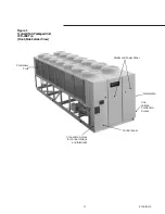
Страница 13: ...13 RTAA IOM 3 Figure 3 Typical RTAA Packaged Unit 240 400 Tons Control Panel Evaporator Outlet Inlet ...
Страница 24: ...24 RTAA IOM 3 ...
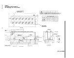
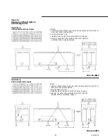
Страница 26: ...26 RTAA IOM 3 Figure 9 Dimensions and Clearances for RTAA Packaged Unit 130 to 200 Ton RTAA SU 1000E ...
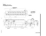
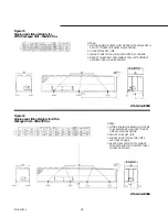
Страница 27: ...27 RTAA IOM 3 Figure 10 Dimensions and Clearances for RTAA Packaged Unit 240 300 Ton RTAA SU 1001C ...
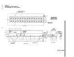
Страница 28: ...28 RTAA IOM 3 Figure 11 Dimensions and Clearances for RTAA Packaged Unit 340 to 400 Ton RTAA SU 1002C ...
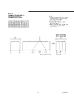
Страница 38: ...38 RTAA IOM 3 RTAA SA 2002C Figure 19 Spring Isolator Placement for Typical RTAA Packaged Unit 240 400 Tons ...
Страница 46: ...46 RTAA IOM 3 Figure 24 Typical Domestic Water Heater Piping Figure 25 Typical Domestic Water Heater Piping ...
Страница 50: ...50 RTAA IOM 3 Figure 30 Refrigerant Circuit Identification ...
Страница 52: ...52 RTAA IOM 3 Figure 31 Remote Evaporator Piping Example ...
Страница 58: ...58 RTAA IOM 3 Continued on Next Page Figure 34 Typical Field Wiring for RTAA Packaged Unit 130 to 200 Tons ...
Страница 59: ...59 RTAA IOM 3 Continued from Previous Page See Notes on Next Page ...
Страница 61: ...61 RTAA IOM 3 Figure 35 Typical Field Wiring for RTAA Packaged Unit 240 400 Tons Continued on Next Page ...
Страница 63: ...63 RTAA IOM 3 Continued from Previous Page See Notes on Page 61 ...
Страница 64: ...64 RTAA IOM 3 Figure 36 Typical Field Wiring for RTAA With Remote Evaporator Option Continued on Next Page ...
Страница 65: ...65 RTAA IOM 3 Continued from Previous Page See Notes on Page 61 ...
Страница 76: ...76 RTAA IOM 3 ...
Страница 78: ...78 RTAA IOM 3 Figure 40 Refrigeration System and Control Components Single Circuit Continued on Next Page ...
Страница 80: ...80 RTAA IOM 3 Figure 41 Refrigeration System and Control Components Duplex Circuit Continued on Next Page ...
Страница 92: ...92 RTAA IOM 3 Figure 51 Operator Interface Controls ...
Страница 120: ...120 RTAA IOM 3 ...
Страница 126: ...126 RTAA IOM 3 Figure 56 Unit Sequence of Operation RTAA 240 to 400 Tons Continued on Next Page ...
Страница 127: ...127 RTAA IOM 3 Continued from Previous Page 2307 1566C ...
Страница 128: ...128 RTAA IOM 3 Figure 57 Unit Sequence of Operation RTAA 130 to 200 Tons 2306 9122A ...
Страница 132: ...132 RTAA IOM 3 Figure 58 Operator s Log ...
Страница 138: ...138 RTAA IOM 3 ...

