98
RTAA-IOM-3
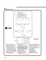
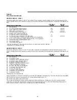
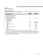
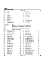
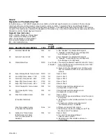
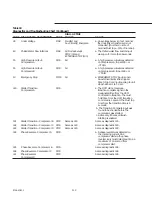
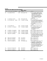
Figure 53
Condition/Diagnostic Codes
UNIT OPERATING STATUS
COMPRESSOR OPERATING STATUS
CODE
DESCRIPTION
CODE
DESCRIPTION
Blank
UCM Power Off
00
Compressor Stop
888888.8
UCM Paw Up
16
Compressor Lockout
00
Unit Stop
17
Cprsr Service Pumpdown
01
Auto-Local
70
Cprsr Restart Inhibit
02
Auto-Remote
72
Cprsr Start
17
Service Pumpdown
74
Run Normal
70
Unit Restart Inhibit
75
Run: Current Limit
72
Unit Start
76
Run: Condenser Limit
74
Run:Normal
77
Run: Evaporator Limit
75
Run:Current Limit
7E
Run:Unload
78
Run:Condenser Limit
77
Run:Evaporator Limit
7E
Run:Unload
88
Reset
DIAGNOSTIC TYPES
100
External Unit Stop
101
Ice Building Complete
MMR
Machine Shutdown-Manual Reset
118
EXV Test
CMR
Circuit Shutdown-Man Reset
174
Ice Building; Normal
MAR
Machine Shutdown-Auto Reset
175
Ice Building: Current Limit
CAR
Circuit Shutdown-Auto Reset
176
Ice Building: Condenser Limit
IFW
Informational-Warning
177
Ice Building: Evaporator Limit
200
Low Ambient Run Inhibit
UNIT DIAGNOSTICS CONDITION
FLASHING DISPLAY:
MEANS:
A xxx
A New CMR, CAR. or IFW Diagnostic Exists.
A xxx
↔
C yyy
Operating Code when MMR or MAR occurred. Diagnostic currently inhibiting operation.
b yyy
Manual reset required to restore full operation. This or other latching diagnostics exist.
C yyy
Condition creating MAR, CAR or IFW still exists. If MMR or CMR, manual reset required.
10 uu
The chilled water setpoint is too close to a cutout setpoint.
DASHES:
MEANS:
d ----
The chiller is in either ice bldg or ice bldg compl; Ivg chld wtr stpt is not applicable.
33 ----
The chiller is in normal cooling; the active ice termination setpoint is not applicable.
Other (e.g. 14----)
Option either not installed or not enabled.
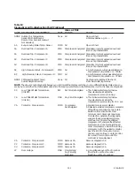
CODE
DESCRIPTION
TYPE
CODE DESCRIPTION
TYPE
87
Chock External Chilled Water Stpt
IFW
19F
Phase Loss - Cprsr D
CMR
89
Check External Current Limit Stpt
IFW
1AO
Power Loss - Cprsr A
CAR
8A
Chilled Water Flow (Ent Wtr Temp)
MMR
1A1
Power Loss - Cprsr 8
CAR
8E
Evap Entering Water Temp Sensor
MMR
1A2
Power Loss - Cprsr C
CAR
8F
Cond Rfgt Tamp Sensor - Ckt I
CMR
1A3
Power Loss - Cprsr D
CAR
90
Cond Rfgt Temp Sensor - Ckt 2
CMR
1A4
Remote communications Loss
IFW
93
Evap Rfgt Temp Sensor - Ckt I
CMR
1A5
Oil Flow Control - Cprsr A
CMR
94
Evap Rfgt Tamp Sensor - Ckt 2
CMR
1A6
Oil Flow Control - Cprsr B
CMR
A0
Zone Temp Sensor
IFW
1A7
Oil Flow Control - Cprsr C
CMR
A1
Outdoor Air Temp Sensor
IFW
1A8
Oil Flow Control - Cprsr D
CMR
Ab
Evap Leaving Wtr Temp Sensor
MMR
1A9
EXV Elec Drive Ckt - Rfgt Ckt I
CMR
bA
Overload Trip - Cprsr A
CMR
1AA
EXV Elec Drive Ckt - Rfgt Ckt 2
CMR
bb
Overload Trip - Cprsr 0
CMR
1Ad
Memory Error Type I (See Oper Manual)
IFW
bC
Overload Trip - Cprsr C
CMR
1AE
Low Differential Press - Ckt I
CMR
bd
Overload Trip - Cprsr D
CMR
1AF
Low Differential Press - Ckt 2
CMR
bE
High Pressure Cutout - Cprsr C
CMR
1b2
Severe Phase Unbalance - Cprsr A
CMR
bF
High Pressure Cutout - Cprsr D
CMR
1b3
Severe Phase Unbalance - Cprsr B
CMR
C5
Low Chilled Water Temp (Unit off)
IFW
1b4
Severe Phase Unbalance - Cprsr C
CMR
C6
Low Chilled Water Temp (Unit on)
MAR
1b5
Severs Phase Unbalance - Cprsr 0
CMR
CA
Contactor - Cprsr A
MMR
1b6
Compressor Overload Setting - Cprsr A
IFW
Cb
Contactor - Cprsr B
MMR
1b7
Compressor Over load Setting - Cprsr B
IFW
cc
Contactor - Cprsr C
MMR
1b8
Compressor Overload Setting - Cprsr C
IFW
Cd
Contactor - Cprsr D
MMR
1b9
Compressor Overload Setting - Cprsr D
IFW
d7
Over Voltage
MAR
1bA
Phase Unbalance - Cprsr A
CMR
d8
Under Voltage
MAR
1bb
Phase Unbalance - Cprsr 8
CMR
Ed
Chilled Water Flow Interlock
MAR
1bC
Phase Unbalance - Cprsr C
CMR
F5
High Pressure Cutout - Cprsr A
CMR
1bd
Phase Unbalance - Cprsr D
CMR
F6
High Pressure Cutout - Cprsr B
CMR
1bE
Winding Temp. - Cprsr A
CMR
Fd
Emergency Stop Input
MMR
1bF
Winding Temp. - Cprsr B
CMR
180
Starter Transition - Cprsr A
CMR
1C0
Winding Temp. - Cprsr C
CMR
181
Starter Transition - Cprsr B
CMR
1C1
Winding Temp. - Cprsr D
CMR
182
Starter Transition - Cprsr C
CMR
1C2
Discharge Temp. - Cprsr A
CMR
183
Starter Transition - Cprsr D
CMR
1C3
Discharge Temp. - Cprsr 8
CMR
184
Phase Reversal - Cprsr A
CMR
1C4
Discharge Temp. - Cprsr C
CMR
185
Phase Reversal - Cprsr 8
CMR
1C5
Discharge Temp. - Cprsr D
CMR
186
Phase Reversal - Cprsr C
CMR
1C6
High Differential Pressure - Ckt I
CMR
187
Phase Reversal - Cprsr D
CMR
1C7
High Differential Pressure - Ckt 2
CMR
190
Low Superheat - Ckt I
CMR
1d1
Memory Error Type 11 (See Oper Manual)
IFW
191
Low Superheat - Ckt 2
CMR
1d2
Memory Error Type III (See Oper Manual)
IFW
194
Low Evap Rfgt Tamp - Ckt I
CMR
1d3
Cprsr Suction Temp. Sensor - Ckt 1
CMR
195
Low Evap Rfgt Temp - Ckt 2
CMR
1d4
Cprsr Suction Temp. Sensor - Ckt 2
CMR
198
Low Oil I Flow - Cprsr A
CMR
1d7
Phase Reversal Prot. Lost - Cprsr A
CMR
199
Low 01 1 Flow - Cprsr B
CMR
1d8
Phase Reversal Prot. Lost - Cprsr B
CMR
19A
Low Oil Flow - Cprsr C
CMR
1d9
Phase Reversal Prot. Lost - Cprsr C
CMR
19b
Low Oil Flow - Cprsr D
CMR
1dA
Phase Reversal Prot. Lost - Cprsr D
CMR
19C
Phase Loss - Cprsr A
CMR
1db
Slave-Exv Elec Drive Ckt - Rfgt Ckt 1
CMR
19d
Phase Lose - Cprsr B
CMR
1dc
Slave-Exv Elec Drive Ckt - Rfgt Ckt 2
CMR
19E
Phase Loss - Cprsr C
CMR
4xy
See Operator’s Manual
– – –
X3956048201 Rev. B
Condition Codes
Содержание RTAA-130
Страница 2: ... American Standard Inc 1991 ...
Страница 8: ...8 RTAA IOM 3 ...
Страница 13: ...13 RTAA IOM 3 Figure 3 Typical RTAA Packaged Unit 240 400 Tons Control Panel Evaporator Outlet Inlet ...
Страница 24: ...24 RTAA IOM 3 ...
Страница 26: ...26 RTAA IOM 3 Figure 9 Dimensions and Clearances for RTAA Packaged Unit 130 to 200 Ton RTAA SU 1000E ...
Страница 27: ...27 RTAA IOM 3 Figure 10 Dimensions and Clearances for RTAA Packaged Unit 240 300 Ton RTAA SU 1001C ...
Страница 28: ...28 RTAA IOM 3 Figure 11 Dimensions and Clearances for RTAA Packaged Unit 340 to 400 Ton RTAA SU 1002C ...
Страница 38: ...38 RTAA IOM 3 RTAA SA 2002C Figure 19 Spring Isolator Placement for Typical RTAA Packaged Unit 240 400 Tons ...
Страница 46: ...46 RTAA IOM 3 Figure 24 Typical Domestic Water Heater Piping Figure 25 Typical Domestic Water Heater Piping ...
Страница 50: ...50 RTAA IOM 3 Figure 30 Refrigerant Circuit Identification ...
Страница 52: ...52 RTAA IOM 3 Figure 31 Remote Evaporator Piping Example ...
Страница 58: ...58 RTAA IOM 3 Continued on Next Page Figure 34 Typical Field Wiring for RTAA Packaged Unit 130 to 200 Tons ...
Страница 59: ...59 RTAA IOM 3 Continued from Previous Page See Notes on Next Page ...
Страница 61: ...61 RTAA IOM 3 Figure 35 Typical Field Wiring for RTAA Packaged Unit 240 400 Tons Continued on Next Page ...
Страница 63: ...63 RTAA IOM 3 Continued from Previous Page See Notes on Page 61 ...
Страница 64: ...64 RTAA IOM 3 Figure 36 Typical Field Wiring for RTAA With Remote Evaporator Option Continued on Next Page ...
Страница 65: ...65 RTAA IOM 3 Continued from Previous Page See Notes on Page 61 ...
Страница 76: ...76 RTAA IOM 3 ...
Страница 78: ...78 RTAA IOM 3 Figure 40 Refrigeration System and Control Components Single Circuit Continued on Next Page ...
Страница 80: ...80 RTAA IOM 3 Figure 41 Refrigeration System and Control Components Duplex Circuit Continued on Next Page ...
Страница 92: ...92 RTAA IOM 3 Figure 51 Operator Interface Controls ...
Страница 120: ...120 RTAA IOM 3 ...
Страница 126: ...126 RTAA IOM 3 Figure 56 Unit Sequence of Operation RTAA 240 to 400 Tons Continued on Next Page ...
Страница 127: ...127 RTAA IOM 3 Continued from Previous Page 2307 1566C ...
Страница 128: ...128 RTAA IOM 3 Figure 57 Unit Sequence of Operation RTAA 130 to 200 Tons 2306 9122A ...
Страница 132: ...132 RTAA IOM 3 Figure 58 Operator s Log ...
Страница 138: ...138 RTAA IOM 3 ...

