56
RTAA-IOM-3
Leak Test and Evacuation
After installation of the refrigerant
piping, thoroughly test the system for
leaks. Pressure test the system at
pressures required by local codes.
Immediately before evacuation, install
the liquid line filter cores. These will be
shipped with the evaporator.
Note: Do not install these before the
circuit is ready for evacuation, as the
cores will absorb moisture from the
atmosphere.
For field evacuation, use a rotary-type
vacuum pump capable of pulling a
vacuum of 100 microns or less. Follow
the pump manufacturer’s instructions
for proper use of the pump. The line
used to connect the pump to the
system should be copper and be the
largest diameter that can be practically
used. A larger line size with minimum
flow resistance can significantly reduce
evacuation time.
Use the ports on the compressor
suction service valves and the liquid
line shutoff valves for access to the
system for evacuation. Insure that the
compressor suction service valve, the
liquid line shutoff valve, the oil line
shutoff valve and any field installed
valves are open in the proper position
before evacuating.
Insulate the entire suction line and the
suction accumulator line. Where the
line is exposed to the weather, wrap it
with weatherproof tape and seal with
weatherproof compound.
Refrigerant and
Additional Oil Charge
Refrigerant Charge
Determination
The approximate amount of refrigerant
charge required by the system must be
determined by referring to Table 8 and
must be verified by running the system
and checking the liquid line
sightglasses.
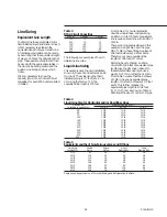
Table 8
System Refrigerant Charge
Circuit Size
Lbs. of R-22
70
130
85
165
100
170
To determine the appropriate charge,
first refer to Table 8 to establish the
required charge required without the
field-installed piping. Next, determine
the charge required for the field-
installed piping by referring to Table 9.
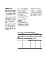
Table 9
Field-installed Piping Charge
Pipe O.D.
Suction
Liquid
(inches)
Line
Line
1 3/8
1.2
63.0
1 5/8
1.7
89.2
2 1/8
2.9
155.2
2 5/8
4.5
239.4
3 1/8
6.4
—
4 1/8
11.3
—
Note: The amounts of refrigerant listed
in Table 9 are based on 100 feet of pipe.
Actual requirements will be in direct
proportion to the actual length of
piping.
Note: Table 9 assumes:
Liquid Temperature = 100 F
Suction Temperature = 35 F
Suction Superheat Temperature = 8 F
The approximate amount of refrigerant
is therefore the sum of the values
determined from Tables 8 and 9.
Example:
Determine the approximate amount of
charge required for an RTAA 200 ton
unit with a remote evaporator that is
located 75 feet away (i.e. the actual
length of field installed pipe is 75 feet
for each suction line and liquid line).
Assume that the suction lines have
been previously determined to be 4 1/8
in., O.D. and the liquid lines are 1 3/8 in.
O.D.
A 200 ton unit has two 100 ton circuits.
From Table 8 above, a 100 ton circuit
requires 170 lbs. of R-22. In addition,
the 4 1/8 in. 0. D. suction line for the 100
ton circuit will require 11.3 lbs. per 100
feet of the 75 feet of line will therefore
require 8.5 lbs. (11.3 times 75/100).
Similarly from Table 9, the 1 3/8 in. O.D.
liquid line will require 47.3 lbs. of R-22
(63 times 75/100). The total R-22 charge
for the 100 ton circuit will be 225.8 lbs.
(170 + 8.5 + 47.3). And because the
RTAA 200 has two 100 ton circuits, the
total system charge will be twice as
much, or 461.6 lbs.
Oil Charge Determination
The unit is factory charged with the
amount of oil required by the system,
without the field-installed piping. The
amount of additional oil required is
dependent upon the amount of
refrigerant that is added to the system
for the field-installed piping.
Use the following formula to calculate
the amount of oil to be added:
Pints of Oil (Trane Oil-15) = lbs. of
refrigerant added for field-installed
piping/18.375
From the example above, in which the
weight of the additional refrigerant
added for the field-installed piping was
55.8 lbs. (47.3 + 8.5), the amount of oil
to be added equals 3 pints (55.8/18.375)
per circuit.
Содержание RTAA-130
Страница 2: ... American Standard Inc 1991 ...
Страница 8: ...8 RTAA IOM 3 ...
Страница 13: ...13 RTAA IOM 3 Figure 3 Typical RTAA Packaged Unit 240 400 Tons Control Panel Evaporator Outlet Inlet ...
Страница 24: ...24 RTAA IOM 3 ...
Страница 26: ...26 RTAA IOM 3 Figure 9 Dimensions and Clearances for RTAA Packaged Unit 130 to 200 Ton RTAA SU 1000E ...
Страница 27: ...27 RTAA IOM 3 Figure 10 Dimensions and Clearances for RTAA Packaged Unit 240 300 Ton RTAA SU 1001C ...
Страница 28: ...28 RTAA IOM 3 Figure 11 Dimensions and Clearances for RTAA Packaged Unit 340 to 400 Ton RTAA SU 1002C ...
Страница 38: ...38 RTAA IOM 3 RTAA SA 2002C Figure 19 Spring Isolator Placement for Typical RTAA Packaged Unit 240 400 Tons ...
Страница 46: ...46 RTAA IOM 3 Figure 24 Typical Domestic Water Heater Piping Figure 25 Typical Domestic Water Heater Piping ...
Страница 50: ...50 RTAA IOM 3 Figure 30 Refrigerant Circuit Identification ...
Страница 52: ...52 RTAA IOM 3 Figure 31 Remote Evaporator Piping Example ...
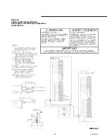
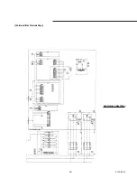
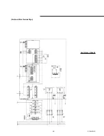
Страница 58: ...58 RTAA IOM 3 Continued on Next Page Figure 34 Typical Field Wiring for RTAA Packaged Unit 130 to 200 Tons ...
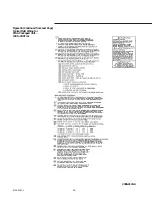
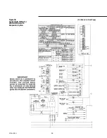
Страница 59: ...59 RTAA IOM 3 Continued from Previous Page See Notes on Next Page ...
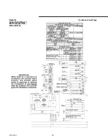
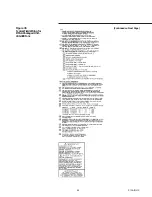
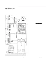
Страница 61: ...61 RTAA IOM 3 Figure 35 Typical Field Wiring for RTAA Packaged Unit 240 400 Tons Continued on Next Page ...
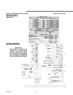
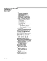
Страница 63: ...63 RTAA IOM 3 Continued from Previous Page See Notes on Page 61 ...
Страница 64: ...64 RTAA IOM 3 Figure 36 Typical Field Wiring for RTAA With Remote Evaporator Option Continued on Next Page ...
Страница 65: ...65 RTAA IOM 3 Continued from Previous Page See Notes on Page 61 ...
Страница 76: ...76 RTAA IOM 3 ...
Страница 78: ...78 RTAA IOM 3 Figure 40 Refrigeration System and Control Components Single Circuit Continued on Next Page ...
Страница 80: ...80 RTAA IOM 3 Figure 41 Refrigeration System and Control Components Duplex Circuit Continued on Next Page ...
Страница 92: ...92 RTAA IOM 3 Figure 51 Operator Interface Controls ...
Страница 120: ...120 RTAA IOM 3 ...
Страница 126: ...126 RTAA IOM 3 Figure 56 Unit Sequence of Operation RTAA 240 to 400 Tons Continued on Next Page ...
Страница 127: ...127 RTAA IOM 3 Continued from Previous Page 2307 1566C ...
Страница 128: ...128 RTAA IOM 3 Figure 57 Unit Sequence of Operation RTAA 130 to 200 Tons 2306 9122A ...
Страница 132: ...132 RTAA IOM 3 Figure 58 Operator s Log ...
Страница 138: ...138 RTAA IOM 3 ...

