background image

115

RTAA-IOM-3

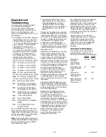
Table 18
Diagnostics and Troubleshooting Chart (Continued)

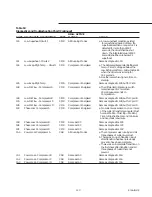
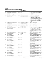
DIAG. ACTIVE

CODE DIAGNOSTIC DESCRIPTION

TYPE

MODES

CAUSE

1Ad

 Memory Error Type I

 IFW

UCM Power Up or

a. On UCM power up or following a

Following a Type II

Type II Memory Error a NOVRAM

Memory Error

memory error was detected. The UCM

is operating on all Engineering ROM
defaults for all setup parameters.
Check all I setup parameters and
continue to run chiller. Replace the
Chiller Module as soon as a
replacement is available.

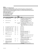
1AE

Low Diff. Pressure - Circuit 1

CMR

Compressor Energized

a. The fan control algorithm detected a

low differential temperature/ pressure
condition that existed for more than
180 contiguous seconds. The trip-
point is 40 PSID.

1AF

Low Diff. Pressure - Circuit 2

CMR

Compressor Energized

Same as diagnostic 1AE.

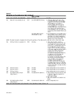
1b2

Severe Phase Unbalance -

CMR

All Running Modes

a. A 30% Phase Unbalance diagnostic

Compressor A

has been detected. The 15% Phase

Unbalance criteria has been defeated.
Items to check are the Current
Transformer Part Numbers (they
should all match), The Current
Transformer resistances, line voltage
phase balance, all power wiring
connections, the contactor pole faces,
and the motor.

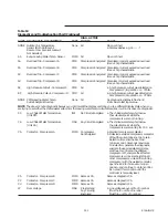
1b3

Severe Phase Unbalance -

CMR

All Running Modes

Same as diagnostic 1b2.

Compressor B

1b4

Severe Phase Unbalance -

CMR

All Running Modes

Same as diagnostic 1b2.

Compressor C

1b5

Severe Phase Unbalance -

CMR

All Running Modes

Same as diagnostic 1b2.

Compressor D

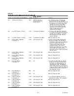
1b6

Overload Setting -

IFW

All

a. The CPM NovRam Based overload

Compressor A

setting did not agree with the MCSP

Dip Switch overload setting for 30
contiguous seconds. The affected
MCSP shall use the minimum (00000
binary, 00 decimal) overload setting as
a default until the UCM is reset when
this diagnostic occurs.

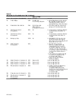
1b8

Overload Setting -

IFW

All

Same as diagnostic 1b6.

Compressor C

1b9

Overload Setting -

IFW

All

Same as diagnostic 1b6.

Compressor D

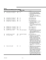
1bA

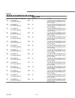
Phase Unbalance -

CMR

All Running Modes

a. A 15% phase unbalance has been

Compressor A

detected. Menu Item “47” is enabled.

1bb

Phase Unbalance -

CMR

All Running Modes

Same as diagnostic 1bA.

Compressor B

1bC

Phase Unbalance -

CMR

All Running Modes

Same as diagnostic 1bA.

Compressor C

1bd

Phase Unbalance -

CMR

All Running Modes

Same as diagnostic 1bA.

Compressor D

Содержание RTAA-130

Страница 1: ...ntinuous product improvement it reserves the right to change specifications and design without notice The installation and servicing of the equipment referred in this booklet should be done by qualified experienced technicians Air Cooled Series R Rotary Liquid Chillers CO and Later Design Sequence Packaged Air Cooled Chiller RTAA 130 400 Remote Evaporator Air Cooled Chiller RTAA 130 200 Models RTA...

Страница 2: ... American Standard Inc 1991 ...

Страница 3: ... 54 Refrigerant Sensors 56 Leak Test and Evacuation 56 Refrigerant and Additional Oil Charge 56 Refrigerant Charge Determination 56 Oil Charge Determination 57 Installation Electrical 57 General Recommendations 68 Installer Supplied Components 68 Remote Evaporator Only 68 Power Supply Wiring 68 General 68 Control Power Supply 68 Heat Tape Power Supply Packaged Units Only 68 Water Pump Power Supply...

Страница 4: ... Temperature Control 106 Chilled Water Reset CWR 107 Leaving Water Temperature Cutout 107 Low Refrigerant Temperature Cutout 107 Low Ambient Temperature Start 107 Low Refrigerant Temperature Cutout Retry 108 Auto Lead Lag 108 Phase Imbalance Protection 108 Reverse Rotation Protection 108 DIP Switch Settings 108 Compressor Overload DIP Switches 108 IPC Address 108 2 10 VDC 4 20 mA Input for CWS and...

Страница 5: ...ing Label 58 Figure 34 Typical Field Wiring for RTAA Packaged Unit 130 to 200 Tons 61 Figure 35 Typical Field Wiring for RTAA Packaged Unit 240 to 400 Tons List of Illustrations 11 Figure 1 Typical RTAA Packaged Unit 130 to 200 Tons Front side Exterior View 12 Figure 2 Typical RTAA Packaged Unit 130 to 200 Tons Rear side Exterior View 13 Figure 3 Typical RTAA Packaged Unit 240 to 400 Tons Front si...

Страница 6: ...urations RTAA 130 to 200 Ton 15 F Minimum Ambient 86 Figure 46 Fan Configurations RTAA 130 to 400 Ton 0 F Minimum Ambient 88 Figure 47 RTAA Control Panel 130 to 200 Tons 89 Figure 48 RTAA Control Panel 240 to 300 Tons 90 Figure 49 RTAA Control Panel 340 to 400 Tons 91 Figure 50 RTAA Control Panel 130 to 200 Tons with Remote Evaporator Option 92 Figure 51 Operator Interface Controls 93 Figure 52 Me...

Страница 7: ...es 56 Table 8 System Refrigerant Charge 56 Table 9 Field installed Piping Charge 67 Table 10 Electrical Data 70 Table 11 Alarm Running Maximum Capacity Relay Output Configurations 70 Table 12 Alarm Running Maximum Capacity Menu Settings 72 Table 13 Input Values vs Extended Chilled Water Setpoint Inputs Ohms 73 Table 14 Input Values vs External Current Unit Setpoint 102 Table 15 Leaving Fluid Tempe...

Страница 8: ...8 RTAA IOM 3 ...

Страница 9: ...t proceed with installation of a damaged unit without sales off ice approval Inspection Checklist To protect against loss due to damage incurred in transit complete the following checklist upon receipt of the unit Inspect the individual pieces of the shipment before accepting the unit Check for obvious damage to the unit or packing material Inspect the unit for concealed damage as soon as possible...

Страница 10: ...lation outdoors Depending upon rated capacity the unit will have two three or four compressors The compressor circuits are completely assembled hermetic packages that are factory piped wired leak tested dehydrated and tested for proper control operation before shipment Note Packaged units are factory charged with refrigerant and oil Remote evaporator units are shipped with a holding charge of nitr...

Страница 11: ...gure 1 Typical RTAA Packaged Unit 130 200 Ton Front Side Exterior View Condenser Coils Connection Access for Control Voltage and Interlocks Starter and Power Panel Nameplate Control Panel Line Voltage Connection Access ...

Страница 12: ...12 RTAA IOM 3 Figure 2 Typical RTAA Packaged Unit 130 200 Ton Rear Side Exterior View Chilled Water Outlet Chilled Water Inlet ...

Страница 13: ...13 RTAA IOM 3 Figure 3 Typical RTAA Packaged Unit 240 400 Tons Control Panel Evaporator Outlet Inlet ...

Страница 14: ...14 RTAA IOM 3 Figure 4 Typical RTAA Unit Rear Exterior View Condenser Fans Motors Condenser Liquid Line Filter Electronic Expansion Valves Liquid Line Filter Condenser ...

Страница 15: ...th Remote Evaporator Option Rear Exterior View Condenser Fans Motors Circuit 1 Condenser Fans Motors Circuit 2 Condenser Circuit 1 Condenser Circuit 2 Circuit 1 Field Refrigerant Piping Connections Circuit 2 Field Refrigerant Piping Connections ...

Страница 16: ...2 42 42 Number of Rows 3 3 3 3 3 3 Condenser Fans Quantity 5 5 5 5 6 5 7 5 7 6 7 7 Diameter In 30 30 30 30 30 30 Total Airflow CFM 105 860 105 860 114 610 120 160 128 910 134 460 Nominal RPM 1140 1140 1140 1140 1140 1140 Tip Speed Ft Min 8954 8954 8954 8954 8954 8954 Motor HP Ea 1 5 1 5 1 5 1 5 1 5 1 5 Min Starting Oper Ambient 2 Std Unit Deg F 15 15 15 15 15 15 Low Amb Deg F 0 0 0 0 0 0 General U...

Страница 17: ...iameter In 30 30 30 30 1 30 30 Total Airflow CFM 173 090 187 390 201 690 240 320 254 620 268 920 Nominal RPM 1140 1140 1140 1140 1140 1140 Tip Speed Ft Min 8954 8954 8954 8954 8954 8954 Motor HP Ea 1 5 1 5 1 5 1 5 1 5 1 5 Min Starting Oper Ambient 2 0 0 0 0 0 0 Deg F General Unit Refrigerant HCFC 22 HCFC 22 HCFC 22 HCFC 22 HCFC 22 HCFC 22 No of Independent Refrigerant Circuits 2 2 2 2 2 2 Min Load...

Страница 18: ...e Circuit 1 Refrigerant Suction Line Circuit 2 Entering Chilled Water Temp Sensors Leaving Chilled Water Temperature Sensor Evaporator Refrigerant Temperature Sensors Electronic Expansion Valve Sight Glass Filter Dryer Terminal Box Refrigerant Liquid Line Circuit 1 ...

Страница 19: ... A 100 B 70 2 100 C 100 300 1 200 A 100 B 100 2 100 C 100 340 1 140 A 70 B 70 2 200 C 100 D 100 370 1 170 A 100 B 70 2 200 C 100 D 100 400 1 200 A 100 B 100 2 200 C 100 D 100 Table 2 RTAA Refrigerant Circuit Designations and Capacities Package Unit 130 200 Remote Evaporator Unit 130 200 P N L COND 1 A COND 2 B Electronic Expansion Valves P N L COND 1 EVAP 1 A COND 2 EVAP 2 B EVAP 1 EVAP 2 240 300 ...

Страница 20: ...ter outlet Where specified provide and install valves in water piping upstream and downstream of evaporator water connections to isolate the evaporator for maintenance and to balance trim system If desired supply and install flow switches in the chilled water piping interlock each switch with proper pump starter to ensure unit can only operate if water flow is established Chilled water flow protec...

Страница 21: ...refrigerant oil Lists unit test pressures Identifies installation operation and maintenance and service data literature Lists drawing numbers for unit wiring diagrams Compressor Nameplate The compressor nameplate provides following information Compressor model number Compressor serial number Compressor electrical characteristics Utilization Range Recommended refrigerant Remote Evaporator Nameplate...

Страница 22: ... Standard Control No communication module B Standard Control With communication module C Deluxe Control No communication module D Deluxe Control With communication module Deluxe control option consists of the following A Cycle counter and hour meter B Under over voltage protection C Remote alarm contacts and compressor run indication D volts 16 Chilled Water Reset 0 None 1 Return water temperature...

Страница 23: ...owing precautionary measures 1 Store the outdoor unit in a secure area 2 At least every three months quarterly check the pressure in the refrigerant circuits to verify that the refrigerant charge is intact If it is not contact a qualified service organization and the appropriate Trane sales off ice ...

Страница 24: ...24 RTAA IOM 3 ...

Страница 25: ... Units with Remote Evaporator Option Foundation Provide rigid non warping mounting pads or a concrete foundation of sufficient strength and mass to support the outdoor unit operating weight i e including completed piping and full operating charges of refrigerant oil and water Refer to Figures 18 thru 21 for unit operating weights Once in place the outdoor unit must be level within 1 4 6 4 mm over ...

Страница 26: ...26 RTAA IOM 3 Figure 9 Dimensions and Clearances for RTAA Packaged Unit 130 to 200 Ton RTAA SU 1000E ...

Страница 27: ...27 RTAA IOM 3 Figure 10 Dimensions and Clearances for RTAA Packaged Unit 240 300 Ton RTAA SU 1001C ...

Страница 28: ...28 RTAA IOM 3 Figure 11 Dimensions and Clearances for RTAA Packaged Unit 340 to 400 Ton RTAA SU 1002C ...

Страница 29: ...29 RTAA IOM 3 Figure 12 Dimensions and Clearances for RTAA Outdoor Unit with Remote Evaporator Option RTAA SU 1003A ...

Страница 30: ...30 RTAA IOM 3 Figure 13 Dimensions and Weights for Remote Evaporator Option RTAA SU 1004A NOTES 1 TOLERANCE 1 8 UNLESS OTHERWISE SPECIFIED 2 ALLOW 8 8 ON EITHER END FOR TUBE REMOVAL ...

Страница 31: ...of suitable strength to support the operating weight Remote evaporator weights and mounting locations are shown in Figure 13 The remote evaporator must be level when installed Be sure to allow adequate clearance for water and refrigerant piping connections performance of service procedures reading of gauges and thermometers and operation of valves Space must be allowed at one end of the evaporator...

Страница 32: ...s through the four six or eight lifting plates provided on the unit Figures 14 thru 17 WARNING To prevent injury or death and unit damage use the lifting method shown in Figures 14 and 17 Attach lifting chains or cables to clevis connectors Each cable alone must be strong enough to lift the chiller Attach cables to lifting beam Total lifting weight lifting weight distribution and required lifting ...

Страница 33: ...ARGE 4 DEDUCT 740 FROM TOTAL WEIGHT FOR UNITS WITHOUT ARCHITECTURAL LOUVER PANELS 130 200 Tons without Domestic Water Heater NOTES 1 LIFTING CHAINS CABLES WILL NOT BE THE SAME LENGTH ADJUST TO KEEP UNIT LEVEL WHILE LIFTING 2 DO NOT FORK LIFT UNIT 3 WEIGHTS ARE TYPICAL FOR UNITS WITH R 22 CHARGE 4 DEDUCT 740 FROM TOTAL WEIGHT FOR UNITS WITHOUT ARCHITECTURAL LOUVERED PANELS 130 200 Tons with Domesti...

Страница 34: ...TH R 22 CHARGE 4 DEDUCT 1166 FROM TOTAL WEIGHT FOR UNITS WITHOUT ARCHITECTURAL LOUVER PANELS NOTES 1 LIFTING CHAINS CABLES WILL NOT BE THE SAME LENGTH ADJUST TO KEEP UNIT LEVEL WHILE LIFTING 2 DO NOT FORK LIFT UNIT 3 WEIGHTS ARE TYPICAL FOR UNITS WITH R 22 CHARGE 4 DEDUCT 1480 FROM TOTAL WEIGHT FOR UNITS WITHOUT ARCHITECTURAL LOUVERED PANELS Figure 16 Rigging and Lifting Weights for RTAA Packaged ...

Страница 35: ...ith Remote Evaporator Option NOTES 1 LIFTING CHAINS CABLES WILL NOT BE THE SAME LENGTH ADJUST TO KEEP UNIT LEVEL WHILE LIFTING 2 DO NOT FORK LIFT UNIT 3 WEIGHTS ARE TYPICAL FOR UNITS WITH R 22 CHARGE 4 DEDUCT 740 FROM TOTAL WEIGHT FOR UNITS WITHOUT ARCHITECTURAL LOUVER PANELS ...

Страница 36: ...ll be necessary to use shims or grout to achieve the required clearance d Minor adjustments can be made to the clearance by turning the leveling bolt clockwise to increase the clearance and counterclockwise to decrease the clearance All eight isolators must be supporting the entire weight of the unit while these adjustments are being made Note If proper clearances cannot be achieved using the leve...

Страница 37: ...37 RTAA IOM 3 RTAA SA 2000B Figure 18 Spring Isolator Placement for Typical RTAA Packaged Unit 130 to 200 Tons without Domestic Water Heater ...

Страница 38: ...38 RTAA IOM 3 RTAA SA 2002C Figure 19 Spring Isolator Placement for Typical RTAA Packaged Unit 240 400 Tons ...

Страница 39: ...39 RTAA IOM 3 RTAA SA 2003A Figure 20 Spring Isolator Placement for Typical RTAA Outdoor Unit with Remote Evaporator Option ...

Страница 40: ...40 RTAA IOM 3 RTAA SA 2008A Figure 21 Spring Isolator Placement for Typical RTAA Unit with Heat Recovery Domestic Water Heater ...

Страница 41: ...nitor the entering and leaving chilled water pressures Caution To prevent damage to chilled water components do not allow evaporator pressure maximum working pressure to exceed 215 psig Provide shutoff valves in lines to the gauges to isolate them from the system when they are not in use Use rubber vibration eliminators to prevent vibration transmission through the water lines If desired install t...

Страница 42: ... chilled water is strictly discretionary but if not installed a signal still must be sent to the chiller to indicate that water flow has been established e g chilled water pump motor starter auxiliary contacts If additional chilled water flow protection is desired use a field installed flow switch or differential pressure switch with the pump interlock to sense system water flow Install and wire t...

Страница 43: ... is shown in Figure 23 Refer to Table 1 for minimum flow recommendations Flow switch contacts are closed on proof of water flow 4 Install a pipe strainer in the entering evaporator water line to protect components from waterborne debris Figure 23 RTAA 130 thru 400 Evaporator Water Pressure Drop ...

Страница 44: ...from differently calibrated gauges installed at unmatched elevations Water Pressure Relief Valves Install a water pressure relief valve in the evaporator inlet piping between the evaporator and the inlet shutoff valve as shown in Figure 22 Water vessels with close coupled shutoff valves have a high potential for hydrostatic pressure buildup on a water temperature increase Refer to applicable codes...

Страница 45: ...unit operating safety These components and their general locations are given below Entering Water Piping Drain Vibration eliminators Shutoff isolation valves Pipe strainer Caution To prevent tube damage install strainer in the water inlet piping Leaving Chilled Water Piping Air vents to bleed air from system Vibration eliminators Shutoff isolation valves Balancing valve Caution To prevent damage d...

Страница 46: ...46 RTAA IOM 3 Figure 24 Typical Domestic Water Heater Piping Figure 25 Typical Domestic Water Heater Piping ...

Страница 47: ...line connections are at one end of the evaporator The installing contractor need only provide and install the refrigerant piping between the evaporator and the outdoor unit System Configuration The system may be configured in either of the two primary arrangements as shown in Figures 26 and 27 The configuration and its associated elevation along with the total distance between the remote evaporato...

Страница 48: ... illustrates what not to do The elevation difference is to not exceed 100 feet C Piping between evaporator and outdoor unit is to not exceed 200 linear feet or an equivalent length includes equivalent length pressure drop of fittings of 300 feet D The suction line must never cross or be above a plane that is 1 8 above the bottom of the outdoor unit Figure 29 illustrates what not to do Figure 27 Re...

Страница 49: ... 27 H The evaporator MUST be matched with its respective outdoor unit The nameplate on the evaporator will have a serial number that is matched to the outdoor unit s serial number See Figure 7 Also the circuits on the outdoor unit must match the circuits on the evaporator I E circuit 1 on the outdoor units must be connected with circuit 1 on the evaporator Caution If the circuits are crossed serio...

Страница 50: ...50 RTAA IOM 3 Figure 30 Refrigerant Circuit Identification ...

Страница 51: ...tion and the Suction Line Sizing sections which follow It is also necessary to know the capacity tons of each circuit Circuit capacities for each RTAA unit are listed in Table 3 The following are examples of how to determine line sizes Liquid Line Sizing This example uses the unit installation shown in Figure 31 and assumes an 85 ton circuit The actual length of field installed piping is 117 feet ...

Страница 52: ...52 RTAA IOM 3 Figure 31 Remote Evaporator Piping Example ...

Страница 53: ...he vertical sections of the line and expanded again for the horizontal sections There are four long radius elbows in this section of piping Using Table 5 and the pipe OD of 3 1 8 in these fittings represent 20 4 feet 4 elbows 5 1 feet each Therefore our new equivalent line length is 45 4 feet 25 20 4 Table 6 indicates that 45 4 equivalent feet still permits the use of 3 1 8 in O D pipe In sizing t...

Страница 54: ...ontaminate the system Use a tubing cutter or heat to remove the end caps When sweating copper joints flow dry nitrogen through the system This prevents scale formation and the possible formation of an explosive mixture of R 22 and air This will also prevent the formation of toxic phosgene gas which occurs when refrigerant is exposed to open flame WARNING To prevent Injury or death due to explosion...

Страница 55: ...55 RTAA IOM 3 Figure 32 Customer Interconnect Wiring for RTAA Outdoor unit with Remote Evaporator 130 to 200 Tons 2306 9133A ...

Страница 56: ...le 9 Field installed Piping Charge Pipe O D Suction Liquid inches Line Line 1 3 8 1 2 63 0 1 5 8 1 7 89 2 2 1 8 2 9 155 2 2 5 8 4 5 239 4 3 1 8 6 4 4 1 8 11 3 Note The amounts of refrigerant listed in Table 9 are based on 100 feet of pipe Actual requirements will be in direct proportion to the actual length of piping Note Table 9 assumes Liquid Temperature 100 F Suction Temperature 35 F Suction Su...

Страница 57: ... unit electrical data are on the unit nameplate and are shown in Table 10 See the unit order specifications for actual electrical data Specific electrical schematics and connection diagrams are shipped with the unit Caution To avoid corrosion and overheating at terminal connections use copper conductors only Do not allow conduit to interfere with other components structural members or equipment Co...

Страница 58: ...58 RTAA IOM 3 Continued on Next Page Figure 34 Typical Field Wiring for RTAA Packaged Unit 130 to 200 Tons ...

Страница 59: ...59 RTAA IOM 3 Continued from Previous Page See Notes on Next Page ...

Страница 60: ...60 RTAA IOM 3 Figure 34 Continued from Last Page Typical Field Wiring for RTAA Packaged Unit 130 to 200 Tons 2306 9123 A ...

Страница 61: ...61 RTAA IOM 3 Figure 35 Typical Field Wiring for RTAA Packaged Unit 240 400 Tons Continued on Next Page ...

Страница 62: ...62 RTAA IOM 3 Figure 35 Continued from Previous Page Typical Field Wiring for RTAA Packaged Unit 240 400 Tons Continued on Next Page See Notes on Previous Page ...

Страница 63: ...63 RTAA IOM 3 Continued from Previous Page See Notes on Page 61 ...

Страница 64: ...64 RTAA IOM 3 Figure 36 Typical Field Wiring for RTAA With Remote Evaporator Option Continued on Next Page ...

Страница 65: ...65 RTAA IOM 3 Continued from Previous Page See Notes on Page 61 ...

Страница 66: ...66 RTAA IOM 3 Figure 36 Continued from Previous Page Typical Field Wiring for RTAA With Remote Evaporator Option ...

Страница 67: ...224 500 350 450 300 3 163 163 163 896 896 896 N A 21 1 3 2 8 1 0 575 327 180 450 300 400 225 3 131 131 131 725 725 725 N A 21 1 3 2 3 1 0 RTAA 340 460 303 406 400 500 350 450 4 122 122 163 163 633 633 896 896 N A 24 1 3 2 8 1 0 575 244 327 300 450 300 400 4 98 98 131 131 512 512 725 725 N A 24 1 3 2 3 1 0 RTAA 370 460 360 406 500 500 450 450 4 163 122 163 163 896 633 896 896 N A 26 1 3 2 8 1 0 575...

Страница 68: ...ct Refer to Figure 1 and Figures 34 thru 36 To provide proper phasing of 3 phase input make connections as shown in Figures 34 thru 36 and as stated on the yellow WARNING label in the starter panel For additional information on proper phasing refer to Unit Voltage Phasing Proper equipment ground must be provided to each ground connection in the panel one on 460 575 volt units and two on 200 230 vo...

Страница 69: ... Auto Stop Then following a one minute delay the chilled water pump is cycled off Chilled water flow indication should be provided between TB3 1 2 on the 1U1 board e g water pump motor starter auxiliaries and or flow switch The wiring for this recommendation is shown in the furnished electrical schematics and connection diagrams Relay 5DL1 is a normally open instantaneous close timed open 1 min ti...

Страница 70: ...ly open contacts The relays can provide three different output configurations as shown in Table 11 and each configuration offers four choices as to how the alarm relay is to respond to a set of diagnostics Table 12 shows the twelve settings available in Menu Item 4E and the diagnostics which are issued for each set of conditions Figure 37 Alarm Running Maximum Capacity Contact Outputs Table 12 Ala...

Страница 71: ...Connections are shown in the field diagrams which are shipped with the unit RTAA 240 400 To install cut strip and wire nut existing wire loop W53 on the P43 connector of the 1U4 module to low voltage leads 568 and 569 Connections are shown in the field diagrams which are shipped with the unit External Circuit Lockout Circuit 2 The UCM provides auxiliary control of a customer specified or installed...

Страница 72: ...0 and a fixed 5 6 Kohm 10 1 4 watt resistor should be used For units with 20 F to 39 F LCWS range a field furnished 25 Kohm linear taper potentiometer 1 0 and a fixed 15 Kohm 1 0 1 4 watt resistor should be used If the potentiometer is to be remotely mounted it and the resistor must be connected to the UCM prior to mounting Then with the UCM display in Menu 0 and the display advanced to Active Chi...

Страница 73: ...nt Limit Setpoint CLS Remote Resistor Potentiometer Voltage Source 2 10 VDC or Current Source 4 20 mA This option allows the external setting of the Current Limit Setpoint independent of the Front Panel Current Limit Setpoint by one of three means 1 A remote resistor potentiometer input fixed or adjustable 2 An isolated voltage input 2 10 VDC 3 An isolated current loop input 4 20 mA Methods 2 and ...

Страница 74: ...ce such as a Tracer a multiple machine controller or a remote display panel A shielded twisted pair connection establishes the bidirectional communications link between the unit control panel and the Tracer multiple machine controller or remote display panel Note The shielded twisted pair conductors must run in a separate conduit Caution To prevent control malfunctions do not run low voltage wirin...

Страница 75: ... plug on the evaporator Vent the chilled water system at high points in the system piping Apply heat tape and insulation as necessary to protect all exposed piping from freeze up Electrical Wiring WARNING To prevent injury or death disconnect electrical power source before completing wiring connections to the unit Caution To avoid corrosion and overheating at terminal connections use copper conduc...

Страница 76: ...76 RTAA IOM 3 ...

Страница 77: ...urn driven by the male rotor Separately housed bearing sets are provided at each end of both rotors The slide valve is located above and moves along the top of the rotors The helical rotary compressor is a positive displacement device The refrigerant from the evaporator is drawn into the suction opening at the end of the motor barrel through a suction strainer screen across the motor and into the ...

Страница 78: ...78 RTAA IOM 3 Figure 40 Refrigeration System and Control Components Single Circuit Continued on Next Page ...

Страница 79: ... valve 20 Saturated evaporator temperature sensor 21 Evaporator waterside drain 22 Leaving water temperature sensor 23 Leaving water connection 24 Entering water connection 25 Entering water temperature sensor 26 Drain with Schrader valve 27 Oil line 28 Entering oil cooler header 29 Leaving oil cooler header 30 Schrader valve with stem depressor 31 Oil line shutoff valve 32 5 micron oil filter 33 ...

Страница 80: ...80 RTAA IOM 3 Figure 41 Refrigeration System and Control Components Duplex Circuit Continued on Next Page ...

Страница 81: ...re sensor 21 Evaporator waterside drain 22 Leaving water temperature sensor 23 Leaving water connection 24 Entering water connection 25 Entering water temperature sensor 26 Drain with Schrader valve 27 Oil line 28 Entering oil cooler header 29 Leaving oil cooler header 30 Schrader valve with stem depressor 31 Oil line shutoff valve 32 5 micron oil filter 33 Master solenoid valve 34 Oil line to loa...

Страница 82: ...f periods To ensure proper lubrication and minimize refrigerant condensation in the compressor a heater is mounted on the bottom of the compressor housing A signal from the UCM energizes this heater during the compressor Off cycle to keep refrigerant from condensing in the compressor The heater element is continuously energized Domestic Water Heater The Domestic Water Heater option utilizes availa...

Страница 83: ...arator and is discharged into the condensing coils Compressor Bearing Oil Supply Oil is injected into the bearing housings located at each end of both the male and female rotors Each bearing housing is vented to compressor suction so that oil leaving the bearings returns through the compressor rotors to the oil separator Compressor Rotor Oil Supply Oil flows through this circuit directly from the ...

Страница 84: ...n the unload solenoid valve is energized and the slide valve moves to the fully unloaded position so the unit always starts fully unloaded Oil Filter Each refrigerant circuit is equipped with replaceable element oil filters The filter s remove any impurities that could foul the solenoid valve orifices and compressor internal oil supply galleries This also prevents excessive wear of compressor roto...

Страница 85: ...140 5 5 4 5 5 respectively 155 6 5 4 6 5 respectively 170 7 5 4 7 5 respectively 185 7 6 4 7 6 respectively 200 7 7 4 7 7 respectively For STANDARD air cooled RTAA Chillers the mapping of UCM outputs to fan staging shall be as follows Fan Contactor 5 Fan Circuit 6 Fan Circuit 7 Fan Circuit Circuit 1 K9 K10 K11 K12 K9 K10 K11 K12 K9 K10 K11 K12 Circuit 2 K13 K14 K15 K16 K13 K14 K15 K16 K13 K14 K15 ...

Страница 86: ...st fan on each single compressor circuit is a Half Airflow Half Pitch Blade Fan The first two fans on each dual compressor circuit are Half Airflow Half Pitch Blade Fans For 0 F AMBIENT OPTION air cooled RTAA Chillers the mapping of UCM outputs to fan staging shall be as follows Fan Contactor 5 10 Fan Circuit 6 12 Fan Circuit 7 14 Fan Circuit Circuit 1 K9 K10 K11 K12 K9 K10 K11 K12 K9 K10 K11 K12 ...

Страница 87: ... The three position switch is used to set chiller operation Digital Display The digital display shows both operating and diagnostic codes compressor status indicators settings of a local setpoints and adjustments actual controlling setpoints specified temperatures specified pressures enable disable status of features and options selection status of Sl units or English units for display of temperat...

Страница 88: ...ors 1K3 1K7 Shorting Contactors 1K9 12 Fan Contactors Circuit 1 1K13 16 Fan Contactors Circuit 2 1S1 1S2 Non fused Disconnect Switch 1T1 Control Power Transformer 1T2 Under Over Voltage Transformer 1T3 5 Compressor Current Transformer Circuit 1 1T6 8 Compressor Current Transformer Circuit 2 1TB1 1TB2 Line Voltage Terminal Blocks 1TB3 Terminal Strip 115 V 1U1 Chiller Module 1U2 Options Module 1U3 E...

Страница 89: ...an Contactors Circuit 2 1S1 1S2 Non fused Disconnect Switch 1T1 Control Power Transformer 1T2 Under Over Voltage Transformer 1T3 8 Compressor Current Transformer Circuit 1 1T9 14 Compressor Current Transformer Circuit 2 1TB1 1TB2 Line Voltage Terminal Blocks 1TB3 1TB4 Terminal Strip 115 V 1U1 Chiller Module 1U2 Options Module 1U3 Expansion Valve Module 1U4 Compressor Protection Module Compressor A...

Страница 90: ... 1S1 1S2 Non fused Disconnect Switch 1T1 Control Power Transformer 1T2 Under Over Voltage Transformer 1T3 8 Compressor Current Transformer Circuit 1 1T9 14 Compressor Current Transformer Circuit 2 1TB1 1TB2 Line Voltage Terminal Blocks 1TB3 1TB4 Terminal Strip 115 V 1U1 Chiller Module 1U2 Options Module 1U3 Expansion Valve Module 1U4 Compressor Protection Module Compressor A 1U5 Compressor Protect...

Страница 91: ...horting Contactors 1K9 12 Fan Contactors Circuit 1 1K13 16 Fan Contactors Circuit 2 1S1 1S2 Non fused Disconnect Switch 1T1 Control Power Transformer 1T2 Under Over Voltage Transformer 1T3 5 Compressor Current Transformer Circuit 1 1T6 8 Compressor Current Transformer Circuit 2 1TB1 1TB2 Line Voltage Terminal Blocks 1TB3 Terminal Strip 115 V 1TB8 1TB9 Terminal Strip 24 V 1U1 Chiller Module 1U2 Opt...

Страница 92: ...92 RTAA IOM 3 Figure 51 Operator Interface Controls ...

Страница 93: ... history in code number sequence Use the Display Up key to return to the top of the list While in the C menu item flashing indicates that the information is currently true whereas steady or non flashing indicates historic data only The digital display will not advance to the next item d until all diagnostics have been displayed If there are no diagnostics to display the data field will be blank fo...

Страница 94: ...DISPLAY MENU 2 Selected by setting the number 2 in the P menu item Compressor Circuit indicators shall not be lit continuously in this menu to indicate which compressors are running As the menu is advanced the appropriate compressor circuit indicator will flash UCM Based Setpoint Display Code and Description Defaults Range P Menu Number 20 Compressor Mode 21 Compressor Suction Refrigerant Temp 22 ...

Страница 95: ... 38 Reset Ratio Setpoint Return 50 10 to 120 Zone 100 50 to 300 Outdoor 10 80 to 80 39 Start Reset Setpoint Return 10 F 4 to 30 F Zone 78 F 55 to 85 F Outdoor 90 F 50 to 130 F 3A Maximum Reset Setpoint Return 5 F 0 to 20 F Zone 5 F 0 to 20 F Outdoor 5 F 0 to 20 F 3b External Circuit Lockout d E d Dashes are displayed for the setpoint when the chiller is not in the Ice Building or Ice Building Comp...

Страница 96: ...ge P Menu Number 40 Leaving water Temp Cutout Setpoint 35 F 10 to 35 F 41 Low Refrigerant Temp Cutout Setpoint 22 F 39 to 35 F 42 Condenser Limit Setpoint HPC 90 80 to 120 43 Lead Lag d E E 44 SI Display Units d E d 45 Unit Line Voltage 460 V 46 Under Over Voltage Protection d E d 47 Phase Imbalance Protection d E E 48 Phase Reversal Protection d E E 49 Superheat Setpoint 8 F 4 to 20 F 4A EXV Cont...

Страница 97: ... running As the menu is advanced the appropriate compressor circuit indicator will flash UCM Based Setpoint Display Code and Description Defaults Range P Menu Number 50 Number of Compressors 1 1 2 3 4 51 Compressor Tons 100 25 30 40 50 60 70 85 100 52 Low Water Temp EXV Gain Compensation d e d 53 Fan Control d E E 54 Fans per Circuit 7 4 5 6 7 8 10 12 14 55 Reduced Inrush Starting d E d 56 Compres...

Страница 98: ...MMR 1A9 EXV Elec Drive Ckt Rfgt Ckt I CMR bA Overload Trip Cprsr A CMR 1AA EXV Elec Drive Ckt Rfgt Ckt 2 CMR bb Overload Trip Cprsr 0 CMR 1Ad Memory Error Type I See Oper Manual IFW bC Overload Trip Cprsr C CMR 1AE Low Differential Press Ckt I CMR bd Overload Trip Cprsr D CMR 1AF Low Differential Press Ckt 2 CMR bE High Pressure Cutout Cprsr C CMR 1b2 Severe Phase Unbalance Cprsr A CMR bF High Pre...

Страница 99: ... or a 4 20 mA 0 10 VDC External CLS Remote e g Tracer setpoints communicated over the serial communications link will be ignored but remote devices can still read all unit control data In the STOP RESET position the UCM is powered but operation of the unit is prevented All outputs are de energized and the chiller is stopped The alarm relay output may be energized if an alarm condition exists If an...

Страница 100: ...3 in Menu 1 but it may also be a setpoint that was loaded from a remote controller such as a Tracer multiple machine controller Menu 1 Service 1 Display 10 Front Panel Chilled Water Setpoint The temperature selected at the UCM for the desired chilled water 11 Design Delta Temp Setpoint The difference between the entering and leaving chilled water temperatures at full load This will be a function o...

Страница 101: ...he compressor on that circuit After start the display will automatically return to d and the UCM will resume its lead lag function of compressor control Menu 3 Auxiliary Options 30 External Chilled Water Setpoint Enables or disables chilled water setpoint from an external control system See discussion in Leaving Chilled Water Temperature Control 31 External Current Limit Setpoint Enables or disabl...

Страница 102: ...luid Temperature Setpoints Chilled Leaving Low Water Water Temp Refrig Temp Recommended Solution Freeze Setpoint F Cut out F Cut out F Ethylene Glycol Point F 40 35 22 0 32 39 34 20 3 38 33 18 6 37 32 17 8 36 31 15 10 25 35 30 14 12 34 29 12 14 33 28 11 15 21 32 27 9 17 31 26 7 19 30 25 6 20 16 29 24 4 21 28 23 2 23 27 22 0 25 10 26 21 1 26 25 20 3 28 24 19 5 29 23 18 6 30 4 22 17 8 31 21 16 10 33...

Страница 103: ...onsiveness If the control appears to be too responsive decrease the setpoint Increase the setpoint if the control appears to be sluggish The UCM based default is designed to handle most applications and adjustment is usually not necessary 4C ICS Address Optional Sets the address at which a remote controller such as a Tracer multiple machine or a remote display panel can find the chiller on a Bidir...

Страница 104: ...ctions RTAA 130 200 Standard Ambient d RTAA 130 200 Low Ambient E RTAA 240 400 All E 59 LATSM Set this menu item to d 5A NNS Set this menu item to d 5b Number of EXV Valves per Circuit Set this menu item per the following unit selections RTAA 130 200 Circuit 1 1 Circuit 2 1 RTAA 240 300 Circuit 1 2 Circuit 2 1 RTAA 340 400 Circuit 1 2 Circuit 2 2 5C Future Option Set this menu item to d for both C...

Страница 105: ...tically re enable the unit Electronic Expansion Valve EXV Test This test can be performed only when the chiller switch is in the STOP RESET position It will confirm proper operation of the electronic expansion valve and the EXV module Once the test has been initiated at the UCM the UCM will 1 Overdrive the EXV closed 1250 steps 2 Overdrive the EXV open 1250 steps 3 Overdrive the EXV closed 1250 st...

Страница 106: ...t before any reset has occurred RESET RATIO is a user adjustable gain START RESET is a user adjustable reference TZONE is the zone temperature TOD is the outdoor temperature TWE is the entering evaporator water temperature TWL is the leaving evaporator water temperature MAXIMUM RESET is a user adjustable limit providing the maximum amount of reset Note When any type of CWR is enabled the UCM will ...

Страница 107: ...ither the front panel or active chilled water temperatures less than 15 F above this cutout temperature and the display will flash the last valid temperature If the leaving water temperature cutout is set upward the UCM will maintain the 15 F minimum and will raise the settings on the front panel and active chilled water setpoints if necessary If the saturated evaporator refrigerant temperature fo...

Страница 108: ...the 15 criteria is enabled it will always display the 15 diagnostic first The 30 criteria is always active when a compressor is running regardless of RLA Reverse Rotation Protection The UCM monitors incoming current during start up and will shutdown the compressor within one second if phase reversal is detected Caution Phase relationships during installation of unit power must be carefully control...

Страница 109: ...ither of the AUTO positions The display will show A 88 for 0 5 to 5 sec following the reset before returning to the display of the operating code The above step will not clear the Other Diagnostic Codes menu item To clear this depress and hold the Display Down key while moving the chiller switch from the STOP RESET position to either of the AUTO positions Mechanical Control Settings The settings f...

Страница 110: ...entering evaporator water fell Ent Wtr Temp Energized below the leaving evap water temp by more than 2 F for 100 F seconds b Causes to trip this diagnostic loss of chilled water flow or a calibration shift in the evap water temp sensors 8E Evap Entering Water Temp Sensor MMR All Open or Short 8F Cond Rfgt Temp Sensor Ckt 1 CMR All Open or Short 90 Cord Rfgt Temp Sensor Ckt 2 CMR All Open or Short ...

Страница 111: ... to a different display state when you are trying to set either the chilled water setpoint or the leaving water temp cutout setpoint as it will in the case of a diagnostic C5 Low Chilled Water Temperature IFW No Circuits Energized a The chilled water temp fell below Unit Off the cutout setpoint while the compressors were not running C6 Low Chilled Water Temperature MAR Any Circuit Energized a The ...

Страница 112: ...all be 0 1 to 1 0 sec 180 Starter Transition CMR a The UCM did not receive a Compressor A transition complete signal in the designated time from the UCM command to transition The must hold time from the UCM transition command is 1 second The Must trip time from the transition time is 6 seconds b The Transition Complete input was found to be shorted before the compressor was started c Active only i...

Страница 113: ...ssor B CMR Compressor Energized Same as diagnostic 198 but for Cprsr B 19A Low Oil Flow Compressor C CMR Compressor Energized Same as diagnostic 198 but for Cprsr C 19b Low Oil Flow Compressor D CMR Compressor Energized Same as diagnostic 198 but for Cprsr D 19C Phase Loss Compressor A CMR Compressor Energized a No current was sensed on one or more of the current transformer inputs Must hold 20 RL...

Страница 114: ...et a 10 or 1 second timer As soon as the differential pressure switch opens 0 8 to 1 2 sec the compressor will be de energized and the sequence ended If the differential pressure switch does not open within 10 seconds the compressor shall be de energized and a CMR diagnostic generated not permitting the compressor to restart Whenever the fan control pressure differential is below 70 PSID or if a d...

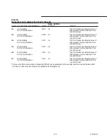
Страница 115: ...Numbers they should all match The Current Transformer resistances line voltage phase balance all power wiring connections the contactor pole faces and the motor 1b3 Severe Phase Unbalance CMR All Running Modes Same as diagnostic 1b2 Compressor B 1b4 Severe Phase Unbalance CMR All Running Modes Same as diagnostic 1b2 Compressor C 1b5 Severe Phase Unbalance CMR All Running Modes Same as diagnostic 1...

Страница 116: ... CMR Compressor Energized a The difference between the condenser pressure and the evaporator pressure exceeded 350 PSID for 0 8 to 5 0 seconds 320 PSID must hold 320 to trip for 1 hour 1C7 High Diff Pressure Circuit 2 CMR Compressor Energized Same as diagnostic 1C6 1d1 Memory Error Type II IFW All a A Shadow RAM memory error was detected The UCM is operating on all last valid values pulled from NO...

Страница 117: ...XV drive circuits on Module 1U3 are faulty 1dC Slaved EXV Elec Drive Circuit CMR On Demand and Same as diagnostic 1db Also refer to Refrigerant Circuit 2 Pre Start diagnostics 1A9 and 1AA 412 1U1 Indicating IFW All The 1U1 Module has detected a loss of 1U2 Communications inter processor communications from the 1U2 Module 413 1U1 Indicating MMR All The 1U1 Module has detected a loss of 1U3 Communic...

Страница 118: ...dule has detected a loss of 1U1 Communications inter processor communications from the 1U1 Module 453 1U5 Indicating CMR All The 1U5 Module has detected a loss of 1U3 Communications inter processor communications from the 1U3 Module 454 1U5 Indicating CMR All The 1U5 Module has detected a loss of 1U4 Communications inter processor communications from the 1U4 Module 461 1U6 Indicating CMR All The 1...

Страница 119: ...f 1U4 Communications inter processor communications from the 1U4 Module 485 1U8 Indicating CMR All The 1U8 Module has detected a loss of 1U5 Communications inter processor communications from the 1U5 Module 486 1U8 Indicating CMR All The 1U8 Module has detected a loss of 1U6 Communications inter processor communications from the 1U6 Module 487 1U8 Indicating CMR All The 1U8 Module has detected a I...

Страница 120: ...120 RTAA IOM 3 ...

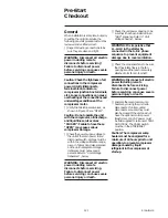
Страница 121: ...alance must not exceed 2 percent Refer to Unit Voltage Imbalance below WARNING Disconnect all electric power including remote disconnects before servicing Failure to disconnect power before servicing can cause severe personal injury or death Check the unit power phasing to be sure that it has been installed in an ABC sequence Refer to Unit Voltage Phasing below WARNING It is imperative that L1 L2 ...

Страница 122: ...ressure drop through the evaporator Refer to Figure 23 Adjust the chilled water flow switch if installed for proper operation Prove Chilled Water Pump Interlock and External Auto Stop as described in Interconnecting Wiring Chilled Water Pump Interlock and External Auto Stop Caution Chilled Water Pump Interlock and External Auto Stop information must be adhered to or equipment damage may occur Chec...

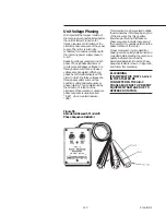
Страница 123: ...n This is determined by the direction of rotation of the alternator When rotation is clockwise phase sequence is usually called ABC when counterclockwise CBA This direction may be reversed outside the alternator by interchanging any two of the line wires It is this possible interchange of wiring that makes a phase sequence indicator necessary if the operator is to quickly determine the phase rotat...

Страница 124: ... the evaporator The flow rates should fall between the minimum and maximum values given in Table 1 Chilled water flow rates below the minimum values will result in laminar flow which reduces heat transfer and causes either loss of EXV control or repeated nuisance low temperature cutouts Flow rates that are too high can cause tube erosion and damage to the tube supports and baffles in the evaporato...

Страница 125: ... flow past the sight glasses should be clear Bubbles in the refrigerant indicate either low refrigerant charge or excessive pressure drop in the liquid line A restriction in the line can sometimes be identified by a noticeable temperature differential between the two sides of the restriction Frost may often form on the line at this point Proper refrigerant charges are shown in Table 1 Caution A cl...

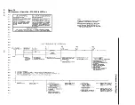
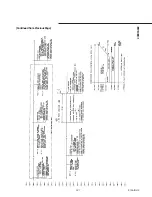
Страница 126: ...126 RTAA IOM 3 Figure 56 Unit Sequence of Operation RTAA 240 to 400 Tons Continued on Next Page ...

Страница 127: ...127 RTAA IOM 3 Continued from Previous Page 2307 1566C ...

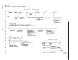
Страница 128: ...128 RTAA IOM 3 Figure 57 Unit Sequence of Operation RTAA 130 to 200 Tons 2306 9122A ...

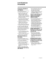
Страница 129: ...illed water pump Lock the switch in the OPEN position Caution Lock the chilled water pump disconnect open to prevent pump damage 3 Close all chilled water supply valves Drain the chilled water from the evaporator If the unit will be exposed to freezing ambient conditions flush the evaporator with an antifreeze solution and energize the evaporator heat tape Caution To prevent damage to the evaporat...

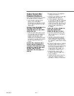
Страница 130: ...wer to the evaporator heat tape connections 4 Check the oil separator oil level See Oil Separator Level Check 5 Fill the evaporator chilled water circuit Refer to Table I for evaporator liquid capacities Vent the system while it is being filled Open the vent on the top of the evaporator during filling and close when filling is completed Caution Do not use untreated or improperly treated water Equi...

Страница 131: ...ly failures Use an Operator s Log such as that shown in Figure 58 to record an operating history for the unit The log serves as a valuable diagnostic tool for service personnel By observing trends in operating conditions an operator can anticipate and prevent problem situations before they occur If the unit does not operate properly during maintenance inspections refer to Diagnostics and Troublesh...

Страница 132: ...132 RTAA IOM 3 Figure 58 Operator s Log ...

Страница 133: ... other fully halogenated refrigerants Be aware of any new leak test methods which eliminate refrigerant as a trace gas 6 When cleaning system components or parts avoid using CFC 11 R 11 or CFC 113 R 113 Refrigeration system cleanup methods which use filters and dryers are preferred Do not use solvents which have ozone depletion factors Properly dispose of used materials 7 Take extra care to proper...

Страница 134: ...to prevent injury or death due to electrical shock Annual Maintenance Perform all weekly and monthly maintenance procedures Check the oil level and refrigerant charge Refer to Maintenance Procedures Have a qualified laboratory perform a compressor oil analysis to determine system moisture content and acid level This analysis is a valuable diagnostic tool Contact a qualified service organization to...

Страница 135: ...tempt to dislodge the material by backflushing the system If unsuccessful after several attempts chemically clean the evaporator Caution Do not use an acid type cleaning agent that will damage steel galvanized steel polypropylene or internal copper components With this information water treatment firms will be able to recommend a suitable chemical for use in this system A typical configuration for...

Страница 136: ...ator charging Schrader valve and the compressor discharge line Schrader valve as shown in Figure 60 Purge to remove non condensibles It is advisable to use Schrader quickcoupler isolation valves at the ends of the hoses These will aid in the installation and removal of the hoses and minimize oil and refrigerant spray 3 After the unit has been off for 10 minutes move the sight glass up and down unt...

Страница 137: ...vel with machine operating Severe oil loss will occur Caution When checking oil level wear protective clothing since oil will spray when discharged Insure that the apex of the line above the sight glass is as high as possible to eliminate liquid traps which can give erroneous readings ...

Страница 138: ...138 RTAA IOM 3 ...

Страница 139: ...ive Ckt Rfgt Ckt I CMR bA Overload Trip Cprsr A CMR 1AA EXV Elec Drive Ckt Rfgt Ckt 2 CMR bb Overload Trip Cprsr 0 CMR 1Ad Memory Error Type I See Oper Manual IFW bC Overload Trip Cprsr C CMR 1AE Low Differential Press Ckt I CMR bd Overload Trip Cprsr D CMR 1AF Low Differential Press Ckt 2 CMR bE High Pressure Cutout Cprsr C CMR 1b2 Severe Phase Unbalance Cprsr A CMR bF High Pressure Cutout Cprsr ...

Страница 140: ...catalog contains listings and prices for all service literature sold by Trane The catalog may be ordered by sending a 15 00 check to The Trane Company Service Literature Sales 3600 Pammel Creek Road La Crosse WI 54601 To help ensure optimum performance be sure to specify quality Trane parts Printed by Production Services La Crosse RTAA IOM 3 ...
Отзывы: