108
RTAA-IOM-3
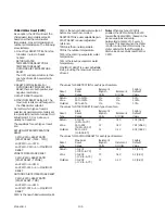
Auto Lead/Lag
This feature is enabled/disabled in code
43, menu 4. When enabled, the UCM
will start the compressor with the
fewest starts and stop the compressor
with the greatest hours, as determined
by the “Compressor Starts”
accumulator (code 29, menu 2) and the
“Compressor Hours” (code 2A, menu
2). (Display is optional). This will tend to
balance out hours and starts equally
over all compressors. For efficiency
improvement, when there are 2
compressors operating, they will be on
opposite circuits. When disabled the
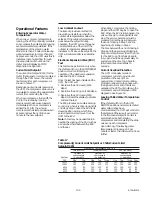
compressors will start per the following
chart.
RTAA
RTAA
RTAA
130-200
240-300
340-400
A
A
A
AB
AC
AC
ABC
ABC
ABCD
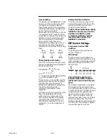
Phase Imbalance Protection
The UCM monitors the current in each
phase and calculates the percentage of
imbalance as follows:
% Imbalance =
(Ix - lave)
x 100
lave
lave = (11 + 12 + 13)
/ 3
lx = phase with greatest difference from
lave (without regard to sign)
If code 47, menu 4, is enabled, and the
average three phase current is greater
than 80% RLA, and the percent of
imbalance is calculated to exceed 15%,
the UCM will shutdown the
compressor and display a CMR
diagnostic.
In addition to the 15% criteria, the UCM
has a non-defeatable 30% criteria
which has its own diagnostic. If the
15% criteria is enabled, it will always
display the 15% diagnostic first. The
30% criteria is always active when a
compressor is running, regardless of
% RLA.
Reverse Rotation Protection
The UCM monitors incoming current
during start-up and will shutdown the
compressor within one second, if
phase reversal is detected.
Caution: Phase relationships during
installation of unit power must be
carefully controlled to assure
compressor protection against
reversed phase rotation. See
Installation - Electrical.
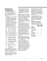
DIP Switch Settings
Compressor Overload DIP
Switches
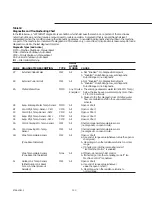
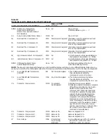
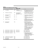
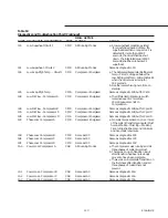
The settings for these switches are
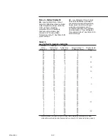
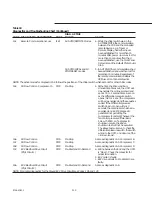
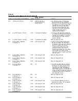
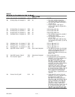
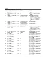
shown in Table 16.
IPC Address
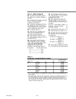
The [PC address set the address for
Inter-Processor Communications of the
UCM modules. The following is the IPC
DIP switch settings for the RTAA 130
400 modules.
IPC
DIP
MODULE
SWITCH
1U3
1U4 1U5 1U6 1U7 1U8
1
OFF
OFF OFF ON ON
OFF
2
OFF
OFF ON OFF ON
ON
2-10 VDC/4-20 made Input for
External Chilled Water Setpoint
(CWS) and Current Limit Setpoint
(CLS)
When either external CWS or external
CLS is used on the optional Module
1U2, DIP switch SW1 positions 1 and/or
2 must be set to accommodate the type
of signal source the customer has
chosen, either 2-10 VDC or 4-20 mA.
SW1 - 1 sets 2-10 VDC/4- 20 mA for
external CWS. SW1 -2 sets 2-10 VDC/4-
20 mA for external CLS. The “OFF’
setting configures the external input for
2-10 VDC; the “ON” setting configures
the external input for 4-20 mA.
Содержание RTAA-130
Страница 2: ... American Standard Inc 1991 ...
Страница 8: ...8 RTAA IOM 3 ...
Страница 13: ...13 RTAA IOM 3 Figure 3 Typical RTAA Packaged Unit 240 400 Tons Control Panel Evaporator Outlet Inlet ...
Страница 24: ...24 RTAA IOM 3 ...
Страница 26: ...26 RTAA IOM 3 Figure 9 Dimensions and Clearances for RTAA Packaged Unit 130 to 200 Ton RTAA SU 1000E ...
Страница 27: ...27 RTAA IOM 3 Figure 10 Dimensions and Clearances for RTAA Packaged Unit 240 300 Ton RTAA SU 1001C ...
Страница 28: ...28 RTAA IOM 3 Figure 11 Dimensions and Clearances for RTAA Packaged Unit 340 to 400 Ton RTAA SU 1002C ...
Страница 38: ...38 RTAA IOM 3 RTAA SA 2002C Figure 19 Spring Isolator Placement for Typical RTAA Packaged Unit 240 400 Tons ...
Страница 46: ...46 RTAA IOM 3 Figure 24 Typical Domestic Water Heater Piping Figure 25 Typical Domestic Water Heater Piping ...
Страница 50: ...50 RTAA IOM 3 Figure 30 Refrigerant Circuit Identification ...
Страница 52: ...52 RTAA IOM 3 Figure 31 Remote Evaporator Piping Example ...
Страница 58: ...58 RTAA IOM 3 Continued on Next Page Figure 34 Typical Field Wiring for RTAA Packaged Unit 130 to 200 Tons ...
Страница 59: ...59 RTAA IOM 3 Continued from Previous Page See Notes on Next Page ...
Страница 61: ...61 RTAA IOM 3 Figure 35 Typical Field Wiring for RTAA Packaged Unit 240 400 Tons Continued on Next Page ...
Страница 63: ...63 RTAA IOM 3 Continued from Previous Page See Notes on Page 61 ...
Страница 64: ...64 RTAA IOM 3 Figure 36 Typical Field Wiring for RTAA With Remote Evaporator Option Continued on Next Page ...
Страница 65: ...65 RTAA IOM 3 Continued from Previous Page See Notes on Page 61 ...
Страница 76: ...76 RTAA IOM 3 ...
Страница 78: ...78 RTAA IOM 3 Figure 40 Refrigeration System and Control Components Single Circuit Continued on Next Page ...
Страница 80: ...80 RTAA IOM 3 Figure 41 Refrigeration System and Control Components Duplex Circuit Continued on Next Page ...
Страница 92: ...92 RTAA IOM 3 Figure 51 Operator Interface Controls ...
Страница 120: ...120 RTAA IOM 3 ...
Страница 126: ...126 RTAA IOM 3 Figure 56 Unit Sequence of Operation RTAA 240 to 400 Tons Continued on Next Page ...
Страница 127: ...127 RTAA IOM 3 Continued from Previous Page 2307 1566C ...
Страница 128: ...128 RTAA IOM 3 Figure 57 Unit Sequence of Operation RTAA 130 to 200 Tons 2306 9122A ...
Страница 132: ...132 RTAA IOM 3 Figure 58 Operator s Log ...
Страница 138: ...138 RTAA IOM 3 ...

