72
RTAA-IOM-3
External Chilled Water
Setpoint (CWS):
Remote Resistor/Potentiometer,
Voltage Source 2-10 VDC, or
Current Source 4-20 mA
This option allows the external setting
of the Chilled Water Setpoint,
independent of the Front Panel Chilled
Water Setpoint, by one of three means:
1. A remote resistor/potentiometer
input (fixed or adjustable)
2. An isolated voltage input 2-10 VDC
3. An isolated current loop input
4-20 mA
Methods 2 and 3 are usually used in
interfacing with a Generic BAS or a
process controller to the chiller.
To enable external setpoint operation,
Item 30 of Menu 3, “External Chilled
Water Setpoint d/E”, should be set to
“E” using the Front Panel Operator
Interface.
1. Remote Resistor/Potentiometer Input
(fixed or adjustable)
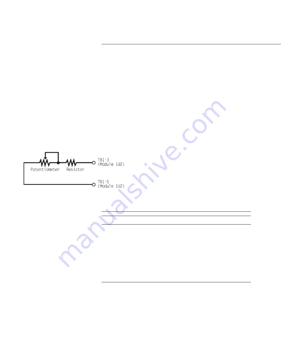
Connect the remote resistor and/or
potentiometer to terminals TB1 -3
and TB1 -5 of Options Module 1U2,
as shown in Figure 38.
For units with 40 F to 60 F LCWS
range, a field-furnished 25 Kohm
linear taper potentiometer (±10%)
and a fixed 5.6 Kohm (±10%) 1/4 watt
resistor should be used.
For units with 20 F to 39 F LCWS
range, a field-furnished 25 Kohm
linear taper potentiometer (±1 0%)
and a fixed 15 Kohm (±1 0%) 1/4 watt
resistor should be used.
If the potentiometer is to be remotely
mounted, it and the resistor must be
connected to the UCM prior to
mounting. Then, with the UCM
display in Menu 0 and the display
advanced to “Active Chilled Water
Setpoint”, the UCM can be used to
calibrate the positions of the
potentiometer to correspond with
the desired settings for the leaving
water temperature. External resistor
input values for various chilled water
setpoints are shown in Table 13.
Table 13
Input Values Vs. External Chilled Water Setpoint
Inputs
Resulting Chilled
Resistance (Ohms)
Current (mA)
Voltage (Vdc)
Water Setpoint (F)
94433
4.0
2.0
0.0
68609
5.2
2.6
5.0
52946
6.5
3.2
10.0
42434
7.7
3.9
15.0
34889
8.9
4.5
20.0
29212
10.2
5.1
25.0
24785
11.4
5.7
30.0
21236
12.6
6.3
35.0
18327
13.8
6.9
40.0
15900
15.1
7.6
45.0
13844
16.3
8.2
50.0
12080
17.5
8.8
55.0
10549
18.8
9.4
60.0
9050
20.0
10.0
65.0
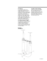
Figure 38
Resistor and Potentiometer
Arrangement for External Chilled
Water Setpoint
Содержание RTAA-130
Страница 2: ... American Standard Inc 1991 ...
Страница 8: ...8 RTAA IOM 3 ...
Страница 13: ...13 RTAA IOM 3 Figure 3 Typical RTAA Packaged Unit 240 400 Tons Control Panel Evaporator Outlet Inlet ...
Страница 24: ...24 RTAA IOM 3 ...
Страница 26: ...26 RTAA IOM 3 Figure 9 Dimensions and Clearances for RTAA Packaged Unit 130 to 200 Ton RTAA SU 1000E ...
Страница 27: ...27 RTAA IOM 3 Figure 10 Dimensions and Clearances for RTAA Packaged Unit 240 300 Ton RTAA SU 1001C ...
Страница 28: ...28 RTAA IOM 3 Figure 11 Dimensions and Clearances for RTAA Packaged Unit 340 to 400 Ton RTAA SU 1002C ...
Страница 38: ...38 RTAA IOM 3 RTAA SA 2002C Figure 19 Spring Isolator Placement for Typical RTAA Packaged Unit 240 400 Tons ...
Страница 46: ...46 RTAA IOM 3 Figure 24 Typical Domestic Water Heater Piping Figure 25 Typical Domestic Water Heater Piping ...
Страница 50: ...50 RTAA IOM 3 Figure 30 Refrigerant Circuit Identification ...
Страница 52: ...52 RTAA IOM 3 Figure 31 Remote Evaporator Piping Example ...
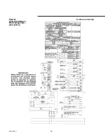
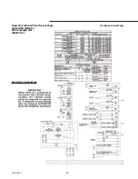
Страница 58: ...58 RTAA IOM 3 Continued on Next Page Figure 34 Typical Field Wiring for RTAA Packaged Unit 130 to 200 Tons ...
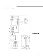
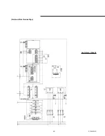
Страница 59: ...59 RTAA IOM 3 Continued from Previous Page See Notes on Next Page ...
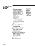
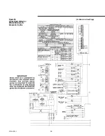
Страница 61: ...61 RTAA IOM 3 Figure 35 Typical Field Wiring for RTAA Packaged Unit 240 400 Tons Continued on Next Page ...
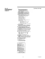
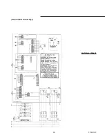
Страница 63: ...63 RTAA IOM 3 Continued from Previous Page See Notes on Page 61 ...
Страница 64: ...64 RTAA IOM 3 Figure 36 Typical Field Wiring for RTAA With Remote Evaporator Option Continued on Next Page ...
Страница 65: ...65 RTAA IOM 3 Continued from Previous Page See Notes on Page 61 ...
Страница 76: ...76 RTAA IOM 3 ...
Страница 78: ...78 RTAA IOM 3 Figure 40 Refrigeration System and Control Components Single Circuit Continued on Next Page ...
Страница 80: ...80 RTAA IOM 3 Figure 41 Refrigeration System and Control Components Duplex Circuit Continued on Next Page ...
Страница 92: ...92 RTAA IOM 3 Figure 51 Operator Interface Controls ...
Страница 120: ...120 RTAA IOM 3 ...
Страница 126: ...126 RTAA IOM 3 Figure 56 Unit Sequence of Operation RTAA 240 to 400 Tons Continued on Next Page ...
Страница 127: ...127 RTAA IOM 3 Continued from Previous Page 2307 1566C ...
Страница 128: ...128 RTAA IOM 3 Figure 57 Unit Sequence of Operation RTAA 130 to 200 Tons 2306 9122A ...
Страница 132: ...132 RTAA IOM 3 Figure 58 Operator s Log ...
Страница 138: ...138 RTAA IOM 3 ...

