116
RTAA-IOM-3
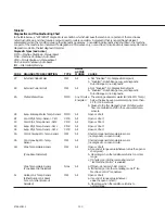
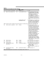
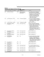
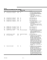
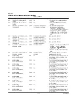
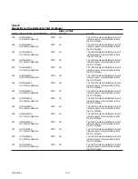
Table 18
Diagnostics and Troubleshooting Chart (Continued)
DIAG. ACTIVE
CODE DIAGNOSTIC DESCRIPTION
TYPE
MODES
CAUSE
1bE
Winding Temp.- Compressor A
CMR
All
a. The motor winding temperature
thermostat opened; nominally 221 F.
b. The motor temperature thermostat or
wiring is open.
c. Time to trip from input open to
compressor shutdown shall be 0.5 to
2.0 seconds.
1bF
Winding Temp.- Compressor B
CMR
All
Same as diagnostic 1bE.
1C0
Winding Temp.- Compressor C
CMR
All
Same as diagnostic 1bE.
1C1
Winding Temp.- Compressor D
CMR
All
Same as diagnostic 1bE.
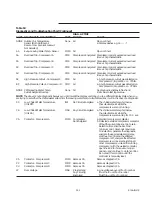
1C2
Discharge Temp.- Compressor A
CMR
All
a. The discharge temperature exceeded
the trip value of 275 F.
b. The discharge temperature PTC or
wiring is open.
Note: on units built in 1992 and later,
the discharge temp sensor will not be
present.
1C3
Discharge Temp. - Compressor B
CMR
All
Same as diagnostic 1C2.
1C4
Discharge Temp. - Compressor C
CMR
All
Same as diagnostic 1C2.
IC5
Discharge Temp. - Compressor D
CMR
All
Same as diagnostic 1C2.
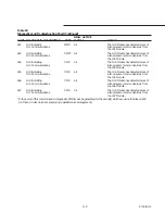
1C6
High Diff. Pressure - Circuit 1
CMR
Compressor Energized
a. The difference between the condenser
pressure and the evaporator pressure
exceeded 350 PSID for 0.8 to 5.0
seconds. 320 PSID must hold, 320+ to
trip for 1 hour.
1C7
High Diff. Pressure - Circuit 2
CMR
Compressor Energized
Same as diagnostic 1C6.
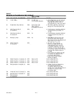
1d1
Memory Error Type II
IFW
All
a. A Shadow RAM memory error was
detected. The UCM is operating on all
last valid values (pulled from
NOVRAM) for all setup parameters.
No setup parameter changes were
pending to be loaded into NOVRAM, a
complete recovery of all setup
parameters was made and there is no
need to check unit setup parameters.
Compressor starts and hours were lost
for not more than the last 24 hours.
This is expected to be an isolated
event and repair or replacement is not
required.
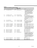
1d2
Memory Error Type III
IFW
All
a. A Shadow RAM memory error was
detected. The UCM is operating on all
last valid values (pulled from
NOVRAM) for all setup parameters.
Setup parameter changes less than 24
hours old pending to be loaded into
NOVRAM were lost. Check all setup
parameters made in last 24 hours.
Compressor starts and hours were lost
for not more than 24 hours. This is
expected to be an isolated event and
repair or replacement is not required.
Содержание RTAA-130
Страница 2: ... American Standard Inc 1991 ...
Страница 8: ...8 RTAA IOM 3 ...
Страница 13: ...13 RTAA IOM 3 Figure 3 Typical RTAA Packaged Unit 240 400 Tons Control Panel Evaporator Outlet Inlet ...
Страница 24: ...24 RTAA IOM 3 ...
Страница 26: ...26 RTAA IOM 3 Figure 9 Dimensions and Clearances for RTAA Packaged Unit 130 to 200 Ton RTAA SU 1000E ...
Страница 27: ...27 RTAA IOM 3 Figure 10 Dimensions and Clearances for RTAA Packaged Unit 240 300 Ton RTAA SU 1001C ...
Страница 28: ...28 RTAA IOM 3 Figure 11 Dimensions and Clearances for RTAA Packaged Unit 340 to 400 Ton RTAA SU 1002C ...
Страница 38: ...38 RTAA IOM 3 RTAA SA 2002C Figure 19 Spring Isolator Placement for Typical RTAA Packaged Unit 240 400 Tons ...
Страница 46: ...46 RTAA IOM 3 Figure 24 Typical Domestic Water Heater Piping Figure 25 Typical Domestic Water Heater Piping ...
Страница 50: ...50 RTAA IOM 3 Figure 30 Refrigerant Circuit Identification ...
Страница 52: ...52 RTAA IOM 3 Figure 31 Remote Evaporator Piping Example ...
Страница 58: ...58 RTAA IOM 3 Continued on Next Page Figure 34 Typical Field Wiring for RTAA Packaged Unit 130 to 200 Tons ...
Страница 59: ...59 RTAA IOM 3 Continued from Previous Page See Notes on Next Page ...
Страница 61: ...61 RTAA IOM 3 Figure 35 Typical Field Wiring for RTAA Packaged Unit 240 400 Tons Continued on Next Page ...
Страница 63: ...63 RTAA IOM 3 Continued from Previous Page See Notes on Page 61 ...
Страница 64: ...64 RTAA IOM 3 Figure 36 Typical Field Wiring for RTAA With Remote Evaporator Option Continued on Next Page ...
Страница 65: ...65 RTAA IOM 3 Continued from Previous Page See Notes on Page 61 ...
Страница 76: ...76 RTAA IOM 3 ...
Страница 78: ...78 RTAA IOM 3 Figure 40 Refrigeration System and Control Components Single Circuit Continued on Next Page ...
Страница 80: ...80 RTAA IOM 3 Figure 41 Refrigeration System and Control Components Duplex Circuit Continued on Next Page ...
Страница 92: ...92 RTAA IOM 3 Figure 51 Operator Interface Controls ...
Страница 120: ...120 RTAA IOM 3 ...
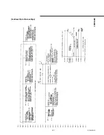
Страница 126: ...126 RTAA IOM 3 Figure 56 Unit Sequence of Operation RTAA 240 to 400 Tons Continued on Next Page ...
Страница 127: ...127 RTAA IOM 3 Continued from Previous Page 2307 1566C ...
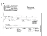
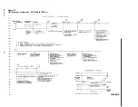
Страница 128: ...128 RTAA IOM 3 Figure 57 Unit Sequence of Operation RTAA 130 to 200 Tons 2306 9122A ...
Страница 132: ...132 RTAA IOM 3 Figure 58 Operator s Log ...
Страница 138: ...138 RTAA IOM 3 ...

